
Variable forward swept wing supersonic aircraft having both low-boom characteristics and low-drag characteristics

a supersonic aircraft and forward swept technology, applied in the direction of wing shapes, transportation and packaging, sustainable transportation, etc., can solve the problems of design not finding, aircraft entire airplane shape, etc., to reduce wave drag, optimize performance, and minimize wave drag

Inactive Publication Date: 2005-10-20
JAPAN AEROSPACE EXPLORATION AGENCY
View PDF13 Cites 51 Cited by
  • Summary
  • Abstract
  • Description
  • Claims
  • Application Information

AI Technical Summary

Benefits of technology

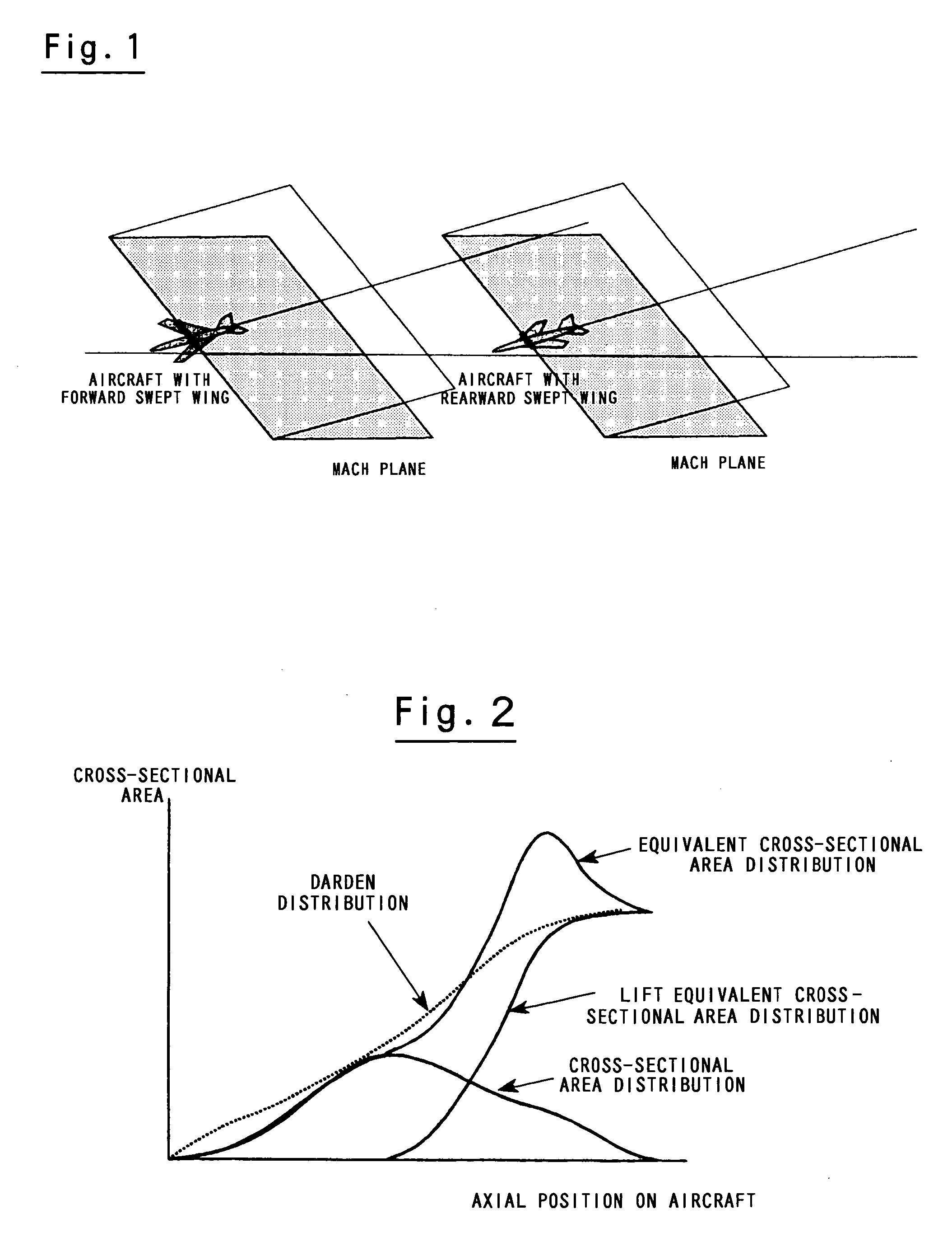
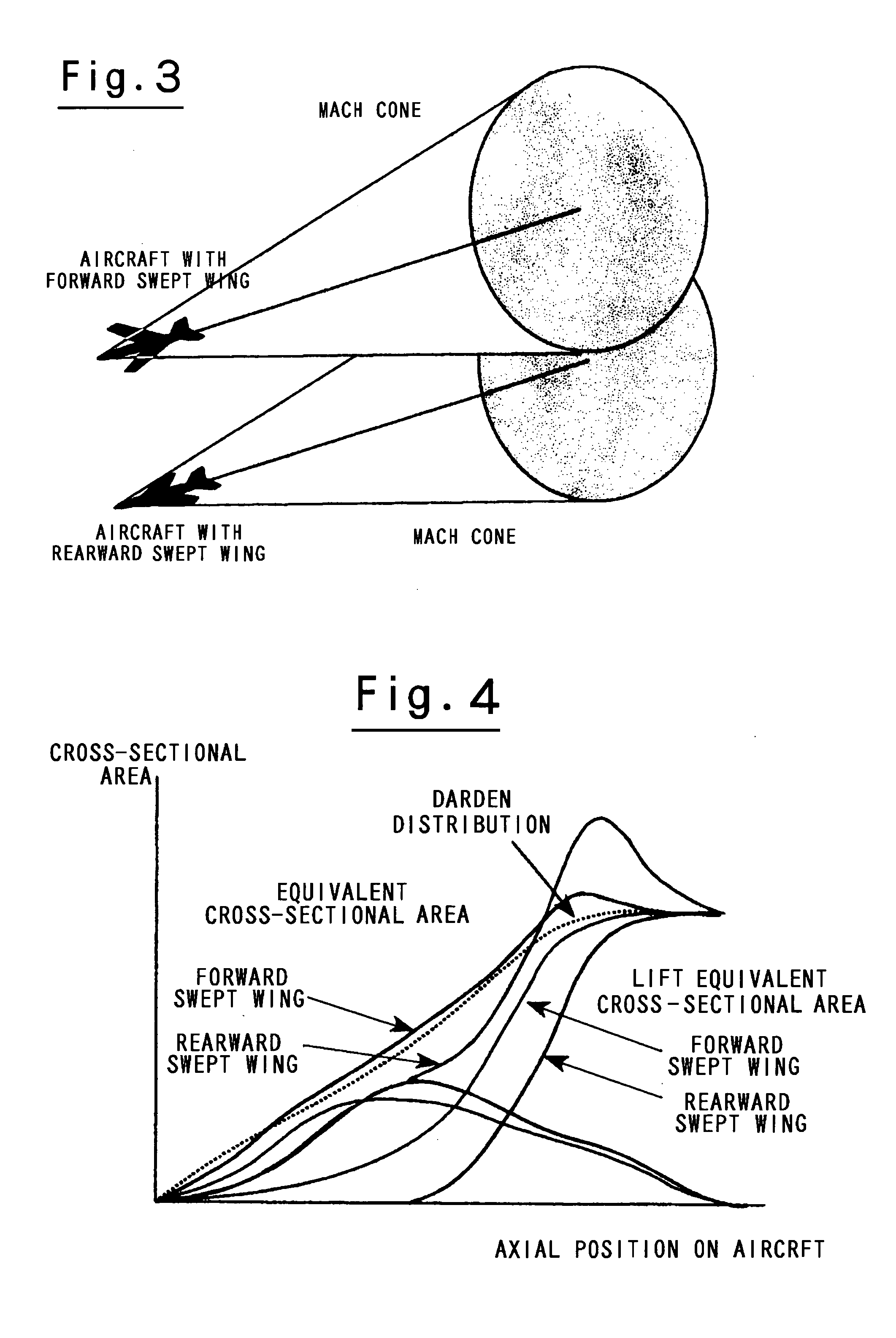
The present invention provides a supersonic aircraft with a unique shape that reduces sonic boom and wave-drag. This is achieved by employing a variable forward swept wing configuration with a mechanism to adjust the forward sweep angle. The forward sweep angle can be reduced to optimize performance during takeoff and landing, and during subsonic flight. In addition, the optimal forward sweep angle for sonic boom reduction can be set by adjusting the forward sweep angle to achieve the optimal lift equivalent cross-sectional area distribution in the axial direction of the aircraft body during supersonic flight. The wing can be set at the forward sweep angle that provides minimal wave-forming drag, so that a forward sweep angle that is concentrated on the improvement of cruise performance can be set. The effect of trim drag can be canceled by increasing the forward sweep angle of the main wing so that the aerodynamic center is moved forward, resulting in minimized trim drag.

Problems solved by technology

However, an aircraft entire airplane shape that achieves both the abovementioned area rule design and the abovementioned low sonic boom design cannot be found, and there have been problems in the development of low-boom supersonic aircraft.

Method used


Image

  • Variable forward swept wing supersonic aircraft having both low-boom characteristics and low-drag characteristics
  • Variable forward swept wing supersonic aircraft having both low-boom characteristics and low-drag characteristics
  • Variable forward swept wing supersonic aircraft having both low-boom characteristics and low-drag characteristics

Examples


examples

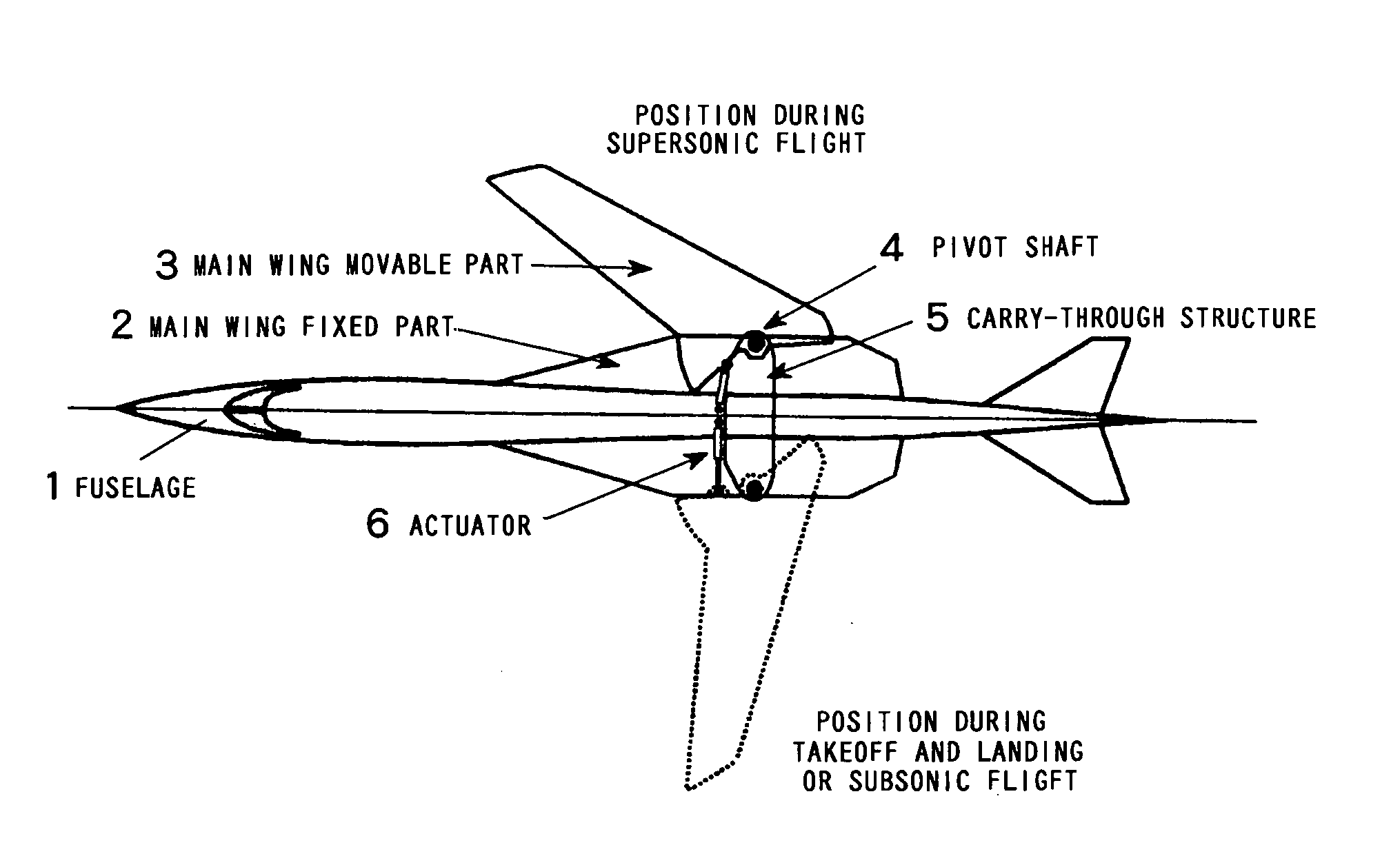
[0038]FIG. 7 shows an example of application of the present invention in a plan view. This figure shows the basic concept of the variable forward swept wing configuration that is proposed in order to manifest optimal performance according to respective flight conditions: namely, during takeoff and landing and subsonic flight, the forward sweep angle of the main wing is set at a small value as indicated by the broken line on the side of the left wing, while during supersonic flight, the angle is set at a large value as indicated by the solid line on the side of the right wing, so that sonic booms during supersonic flight are reduced. Each of the left and right main wings is constructed from a main wing fixed part 2 constituting the inside portion, and a main wing movable part 3 constituting the outside portion. The left and right main wing movable parts 3 are connected to the fuselage 1 or the main wing fixed parts 2 protruding from the fuselage via pivot shafts 4 in the vicinity of ...


PUM


Abstract

It is an object of the present invention to provide the entire airplane shape of a supersonic aircraft that can realize low sonic boom characteristics, and that can also minimize wave-drag. In order to achieve both sonic boom suppression and a reduction in wave-drag, the entire airplane shape of the supersonic aircraft of the present invention uses a variable forward swept wing configuration having a mechanism that can vary a forward sweep angle as the main wing configuration, rather than forming the fuselage shape with a blunt nose.

Description

BACKGROUND OF THE INVENTION [0001] 1. Field of the Invention [0002] The present invention relates the entire airplane shape of a supersonic aircraft, and more specifically relates to an entire airplane shape that reduces wave-forming drag, and suppresses sonic booms. [0003] 2. Description of the Related Art [0004] Generally, in order to satisfy requirements from the standpoints of both economy and environmental compatibility, it is necessary that supersonic aircraft reduce the wave-drag force arising from shock waves, and suppress sonic booms. In the basic approach to reducing wave-drag of a body performing supersonic flight, increasing the slenderness ratio in a case where this body is converted into an equivalent axisymmetrical body is the first condition. As is shown in FIG. 12, this equivalent axisymmetrical body is an equivalent rotational body which has the same cross-sectional area as the cross-sectional area in a case where a certain body position of the aircraft is cut by t...

Claims


Application Information

Patent Timeline
Patent Type & Authority Applications(United States)
IPC IPC(8): B64C3/10B64C3/40B64C30/00
CPCB64C3/10B64C3/40Y02T50/145Y02T50/12B64C30/00Y02T50/10
Inventor HORINOUCHI, SHIGERU
Owner JAPAN AEROSPACE EXPLORATION AGENCY
Learn More