Hanger for use on metal rack

Inactive Publication Date: 2005-10-20
PROTREND ENTERPRISE CO LTD
View PDF3 Cites 27 Cited by
  • Summary
  • Abstract
  • Description
  • Claims
  • Application Information

AI Technical Summary

Benefits of technology

[0010] In the hanger of the present invention, the hook portion is provided along a profile thereof with a substantially vertically extended slit to cut the hook portion into two lateral halves. T

Problems solved by technology

The box 15 of the hanger 14 occupies a large volume and has complicate structure that necessitates relat

Method used


Image

  • Hanger for use on metal rack
  • Hanger for use on metal rack
  • Hanger for use on metal rack

Examples


Embodiment Construction

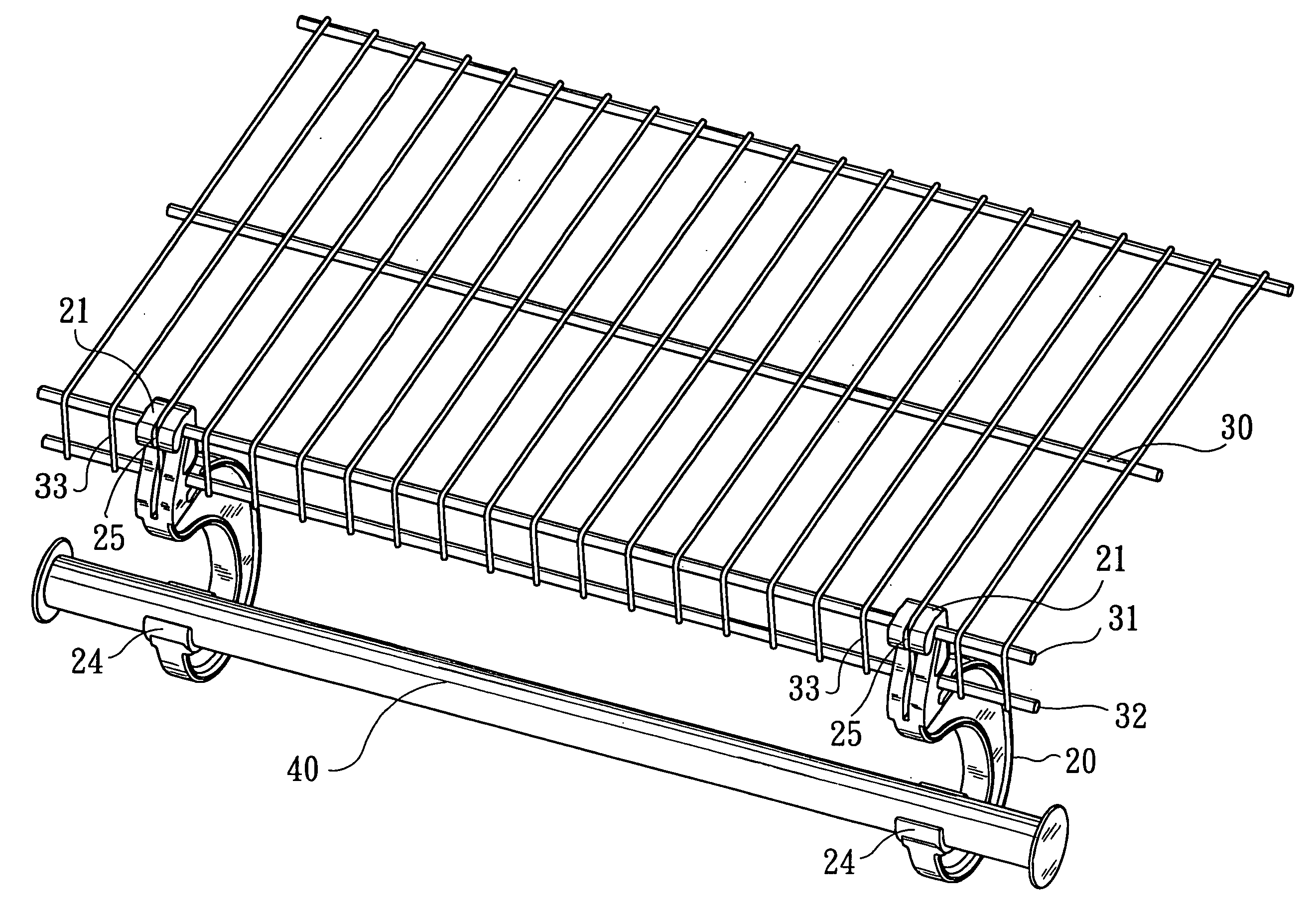
[0019] Please refer to FIG. 3 that is a perspective view of a hanger 20 according to the present invention for use on a metal rack 30 as shown in FIG. 6. The metal rack 30 is fixed to a wall surface using fastening means (not shown), such that a top of the metal rack 30 is in a horizontal position. As can be seen from FIGS. 6 and 7, a predetermined length of a front end of the metal rack 30 is downward bent by 90 degrees to form a vertical front, and an upper and a lower horizontal metal bars 31, 32 are transversely welded to upper and lower end, respectively, of the vertical front to intersect with a plurality of metal wires 33 forming the metal rack 30.

[0020] Please refer to FIGS. 3, 4, and 5 at the same time. The hanger 20 is provided at an upper end with an open-bottomed hook portion 21, at a position closely below and behind the hook portion 21 with at least one horizontal engaging recess 22, 23, and at a lower free end with a supporting seat 24. An inner top of the hook porti...


PUM


Abstract

A hanger for use on metal rack is integrally injection molded and includes a hook portion provided at an upper end thereof, at least one engaging recess located below and behind the hook portion, and a supporting seat provided at a lower free end of the hanger. The hanger is firmly connected to a metal rack by directly hooking the hook portion to an upper horizontal metal bar at a vertical front of the metal rack with the engaging recess engaged with a lower horizontal metal bar at the vertical front of the metal rack. A crossbar may be supported at two ends in the supporting seats of two hangers connected to the metal rack for holding suit hangers thereto.

Description

FIELD OF THE INVENTION [0001] The present invention relates to a hanger for use on metal rack, and more particularly to a hanger that can be directly hooked to a vertical front of a metal rack. BACKGROUND OF THE INVENTION [0002] A metal rack is frequently fixed to a wall surface for holding things, so that valuable space in a room could be fully utilized without the need of spending a lot of money for a custom-made cabinet or closet. The metal rack may be covered with curtains or drapes to define a closed storage space and serves as, for example, a cabinet, a closet, or a wardrobe. When the metal rack is used as a wardrobe, it is desirable a crossbar may be fixed below the metal rack for holding some suit hangers. [0003]FIG. 1 shows a conventional metal rack 10 that includes a vertically downward bent front to increase the structural strength of the metal rack 10, preventing the metal rack 10 from easy deformation. An upper and a lower horizontal metal bar 11, 12 are welded to an up...

Claims


Application Information

Patent Timeline
IPC IPC(8): A47B55/02A47B61/00A47F5/00B42F1/00
CPCA47B55/02A47F5/0006A47B61/003
Inventor CHEN, HENRY
Owner PROTREND ENTERPRISE CO LTD
Why Eureka
Try Eureka