

Fuse state indicator
- Summary
- Abstract
- Description
- Claims
- Application Information
AI Technical Summary
Benefits of technology
Problems solved by technology
Method used
Image

Examples
Embodiment Construction
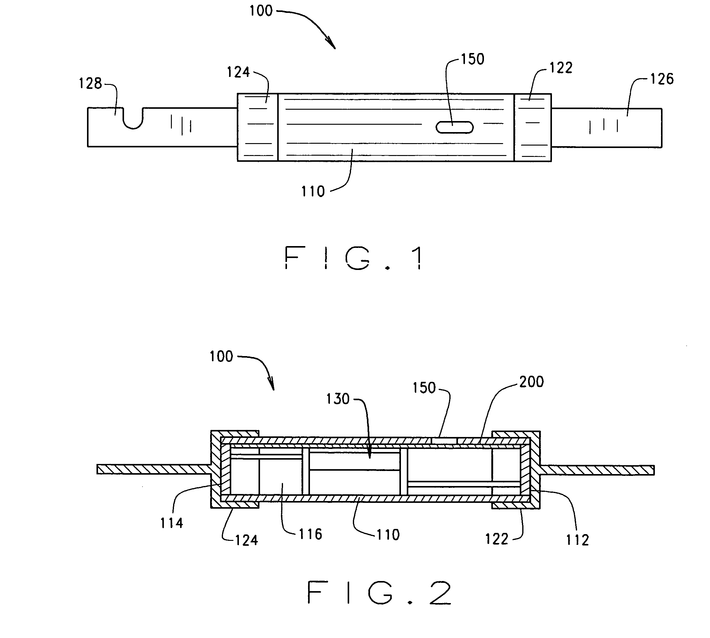
[0019]FIG. 1 is a perspective view of an exemplary embodiment of a fuse 100 including a cylindrical fuse tube or body 110 having an aperture 150 extending therethrough at a location proximate to a first end of fuse body 110, and conductive ferrules or end caps 122, 124 are attached to the fuse body 110 on either end thereof. In an exemplary embodiment, the end caps 122, 124 include knife blades 126, 128 respectively, which may be connected to line side and load side electrical circuitry (not shown), thereby forming a current path through a primary fuse element (not shown in FIG. 1). In accordance with known fuses, the primary fuse element may include one or more fusible links or a fuse element assembly extending through the fuse body 110 between the end caps 122, 124.
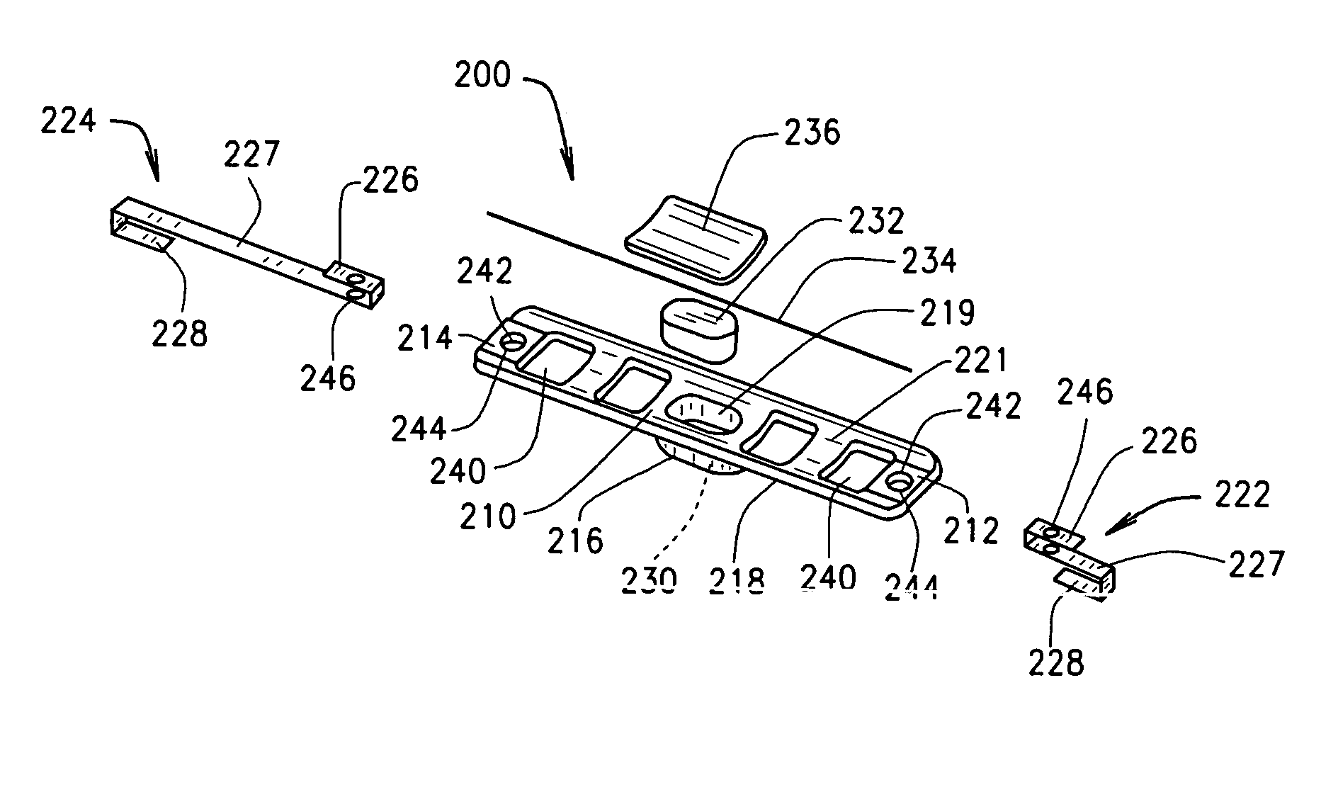
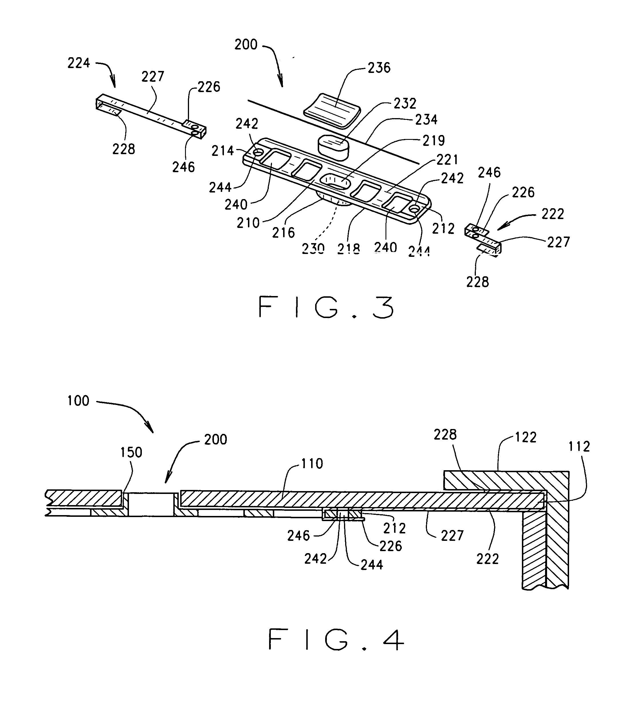
[0020] A fuse state indicator assembly (not shown in FIG. 1) extends interior to the fuse body 110 and a portion of the fuse state indicator is visible through the aperture 150 in the body 110 to indicate an operating ...
PUM
 Abstract
Description
Claims
Application Information