Ejector for motherboard

Inactive Publication Date: 2005-10-20
HON HAI PRECISION IND CO LTD
View PDF6 Cites 11 Cited by
  • Summary
  • Abstract
  • Description
  • Claims
  • Application Information

AI Technical Summary

Benefits of technology

[0006] Accordingly, an object of the present invention is to provide an ejector fo

Problems solved by technology

However, when disengaging a large printed circuit board such as a motherboard from a connector, pulling out the locking portions is a tough work in a narrow inner space of the personal computer or ser

Method used


Image

  • Ejector for motherboard
  • Ejector for motherboard
  • Ejector for motherboard

Examples


Embodiment Construction

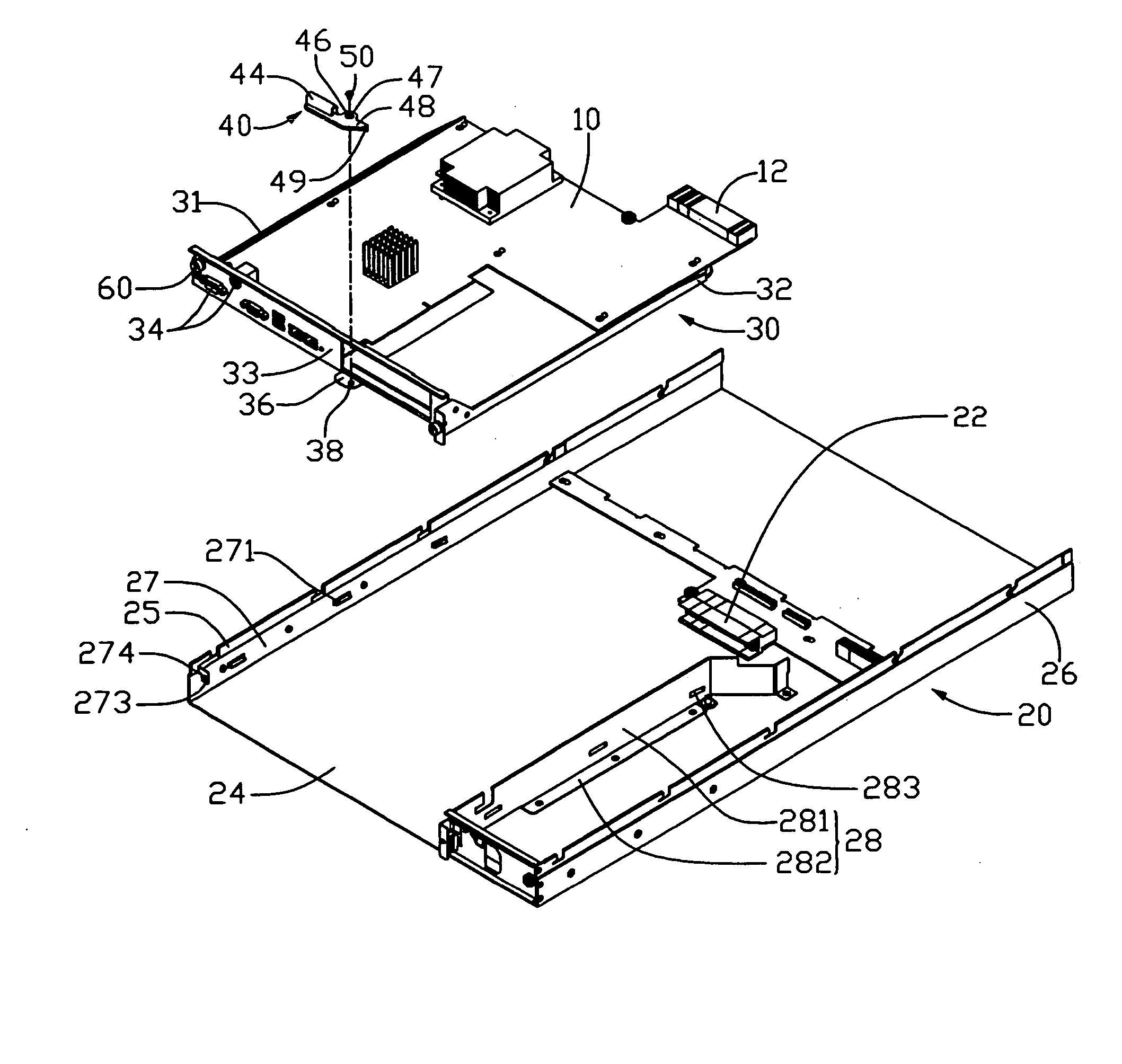
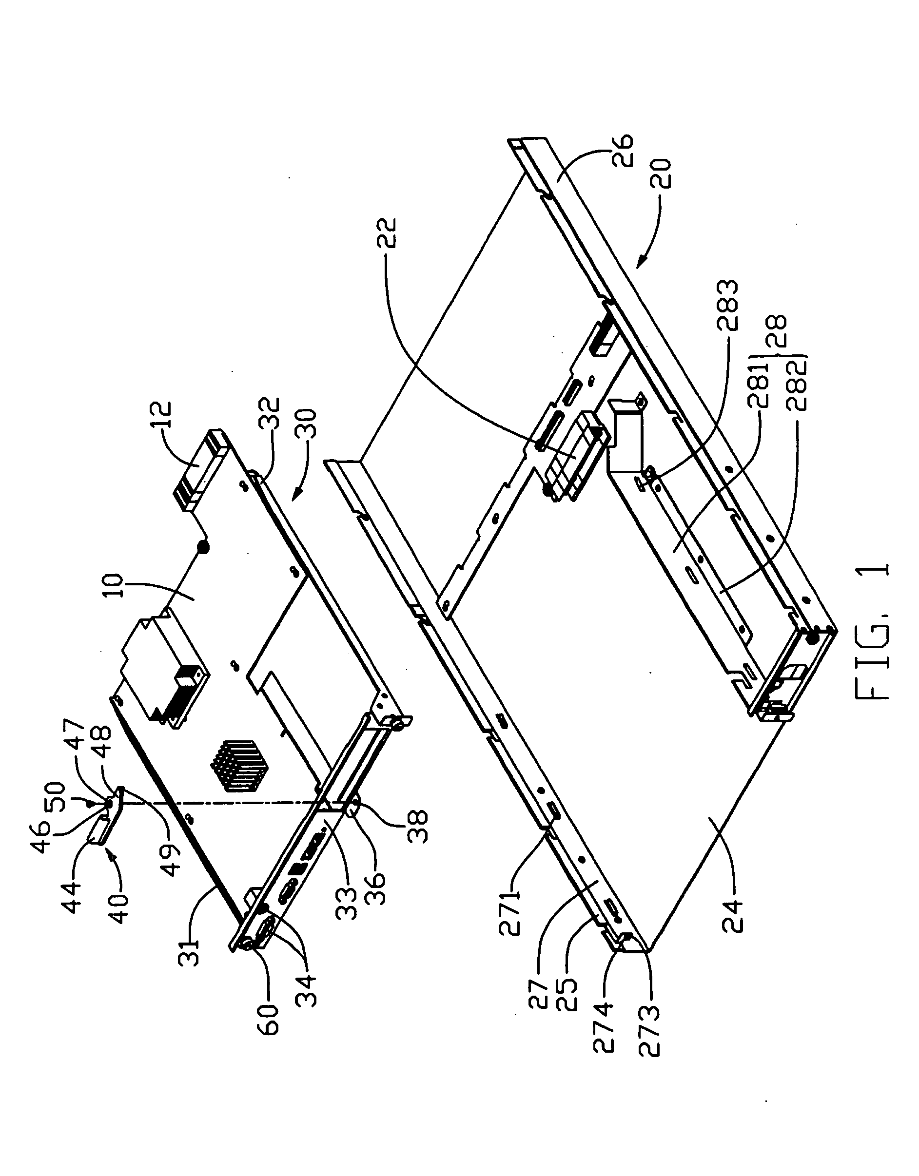
[0015] Referring to FIG. 1, an ejection assembly for an electronic device like a server in accordance with a preferred embodiment of the present invention is used for rapidly ejecting a printed circuit board such as a motherboard 10 from a server chassis 20. The ejection assembly comprises a motherboard tray 30, and an ejector 40.

[0016] The motherboard 10 has a horizontal connecting portion 12 at a rear end thereof. The chassis 20 comprises a bottom plate 24, a left side plate 25, and a right side plate 26. An elongated board 27 is mounted to an inner surface of the left side plate 25. A plurality of bent tabs 271 is stamped inwardly from the elongated board 27. A blocking tab 273 is bent inwardly from a front portion of the elongated board 27 with a threaded hole 274 defined therein. A connector slot 22 is disposed in the chassis 20 corresponding to the connecting portion 12 of the motherboard 10. A partition plate 28 is mounted on the bottom plate 24 of the chassis 20 in the vici...


PUM


Abstract

An ejection assembly as shown is used for rapidly ejecting a motherboard (10) from a server chassis (20). The ejection assembly includes a tray (30) for supporting the motherboard, and an ejector (40). A connector (22) is disposed in the chassis. The ejector is pivotally mounted to the tray, and includes an ejecting portion (48) to abut against a front edge of a bottom plate (24) of the chassis when the motherboard is electronically connected to the connector of the chassis. The ejector is pivoted outwardly so that the ejecting portion presses the front edge of the bottom plate to draw the tray outwardly, the motherboard is thereby horizontally and rapidly ejected from the connector of the chassis.

Description

BACKGROUND OF THE INVENTION [0001] 1. Field of the Invention [0002] The present invention relates to an ejector for a motherboard, and particularly to an ejector which can readily eject a motherboard from a chassis without damaging the motherboard. [0003] 2. Description of the Prior Art [0004] Generally, a personal computer or a server has limited inner space, therefore a printed circuit board is usually horizontally connected with a connecter. An example is disclosed in China Patent No. 02247527.3. A memory of this patent is horizontally connected with a connector of a motherboard. The connector includes an elongated main body and two locking portions secured to opposite sides of the main body. The memory is inserted to the connector and secured by the locking portions. The locking portions must be pulled outwardly, then the memory is manually taken out. This manner is suitable for a small printed circuit board connected to a connector. However, when disengaging a large printed cir...

Claims


Application Information

Patent Timeline
IPC IPC(8): G06F1/16G06F1/18H05K5/02H05K7/10H05K7/14
CPCH05K7/1409G06F1/184
Inventor PENG, WEN-TANGCHENG, CHENG-LUNGSHI, SHU-GANGZHANG, ZHE
Owner HON HAI PRECISION IND CO LTD
Why Eureka
Try Eureka