
Method and apparatus for characterizing an end-to-end path of a packet-based network

a packet-based network and end-to-end path technology, applied in the field of networks, can solve the problems of low accuracy of packet-based network end-to-end path characterization errors, packet-based network end-to-end path dispersion techniques, and evaluation techniques that are sensitive to network path asymmetries,

Inactive Publication Date: 2005-10-20
APPARENT NETWORKS INC
View PDF17 Cites 125 Cited by
  • Summary
  • Abstract
  • Description
  • Claims
  • Application Information

AI Technical Summary

Benefits of technology

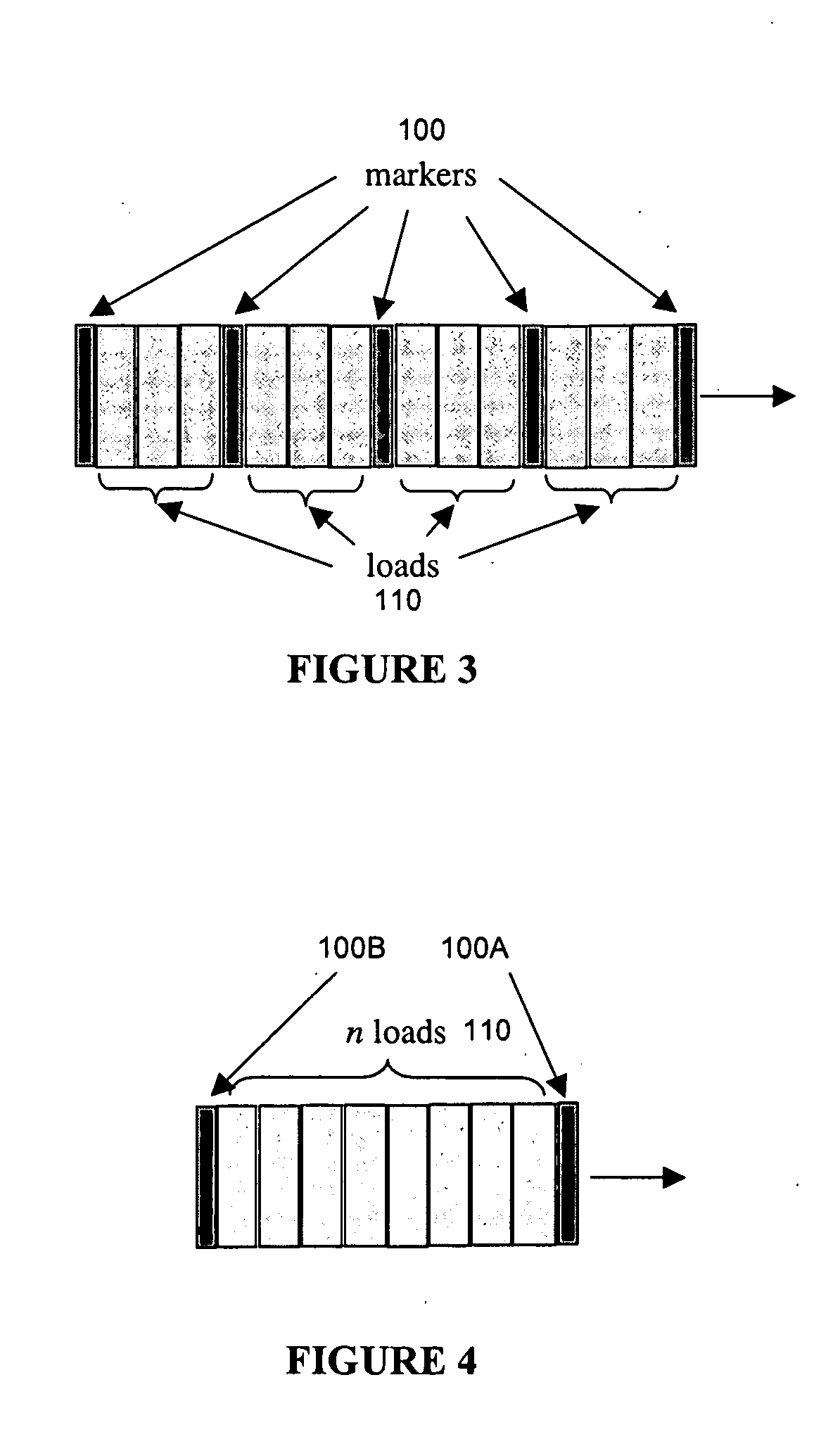
[0014] An object of the present invention is to provide a method and apparatus for characterizing an end-to-end path of a packet-based network. In accordance with an aspect of the present invention, there is provided method for characterizing an end-to-end path of a packet-based network, said method comprising the steps of: generating one or more ordered groups of packets each including two or more marker packets and one or more load packets, all of said packets being configured to travel along a common end-to-end path defined by a source host and a destination host, wherein said one or more load packets are configured to traverse the end-to-end path to a predetermined node, said predetermined node being any node along the end-to-end path; transmitting said one or more ordered groups of packets from said source host along said common end-to-end path; collecting data relating to the transmission of said one or more ordered groups of packets; and analysing said data thereby developing characteristics of the end-to-end path.
[0015] In accordance with another aspect of the invention, there is provided an apparatus for characterizing an end-to-end path of a packet-based network, said apparatus comprising: means for generating one or more ordered groups of packets each including two or more marker packets and one or more load packets, all of said packets being configured to travel along a common end-to-end path defined by a source host and a destination host, wherein said one or more load packets are config

Problems solved by technology

Furthermore, the transmitted packets that are addressed to intermediate hosts between the source and destination can often take alternate routes compared to the path to the destination, thereby resulting in characterization errors of the source-to-destination path.
In addition, these forms of evaluation techniques can be sensitive to asymmetries in the network path.
Packet pair dispersion techniques however, have been criticized for their low accuracy, particularly in the presence of cross traffic.
It is known that the larger packet will typically limit the travel of the smaller following packet due to the greater serialization time the larger packet requires at each forwarding node.
This technique however, is known to have a very low level of accuracy.
Consequently this technique analyzes the delay distributions for specific behaviours in order to determine the applicable analysis, thereby potentially resulting in the requirement of multiple analysis methods.
A disadvantage of this evaluation technique is that high-speed scalability is identified and stated as an issue.

Method used


Image

  • Method and apparatus for characterizing an end-to-end path of a packet-based network
  • Method and apparatus for characterizing an end-to-end path of a packet-based network
  • Method and apparatus for characterizing an end-to-end path of a packet-based network

Examples


Embodiment Construction

Definitions

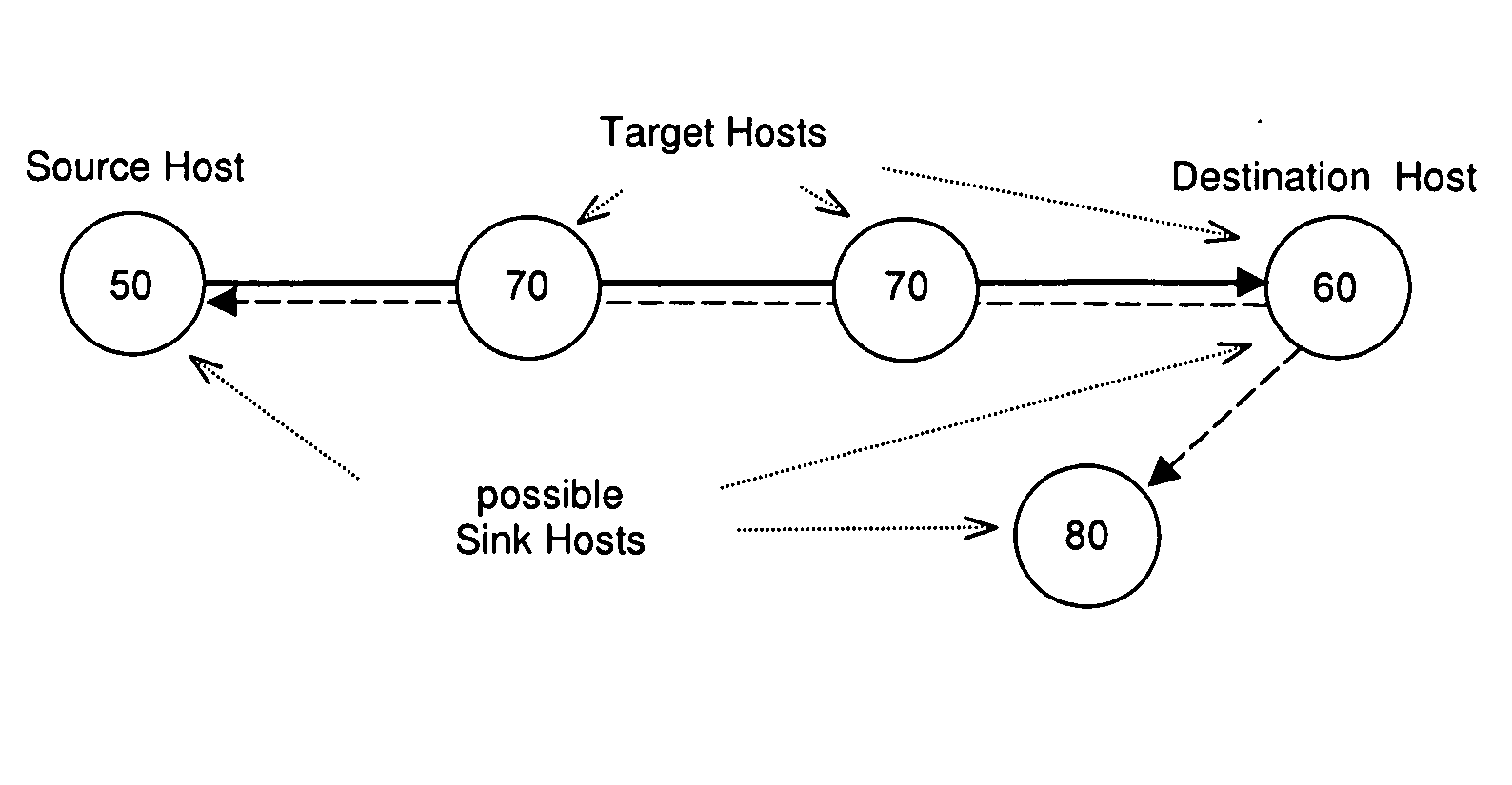
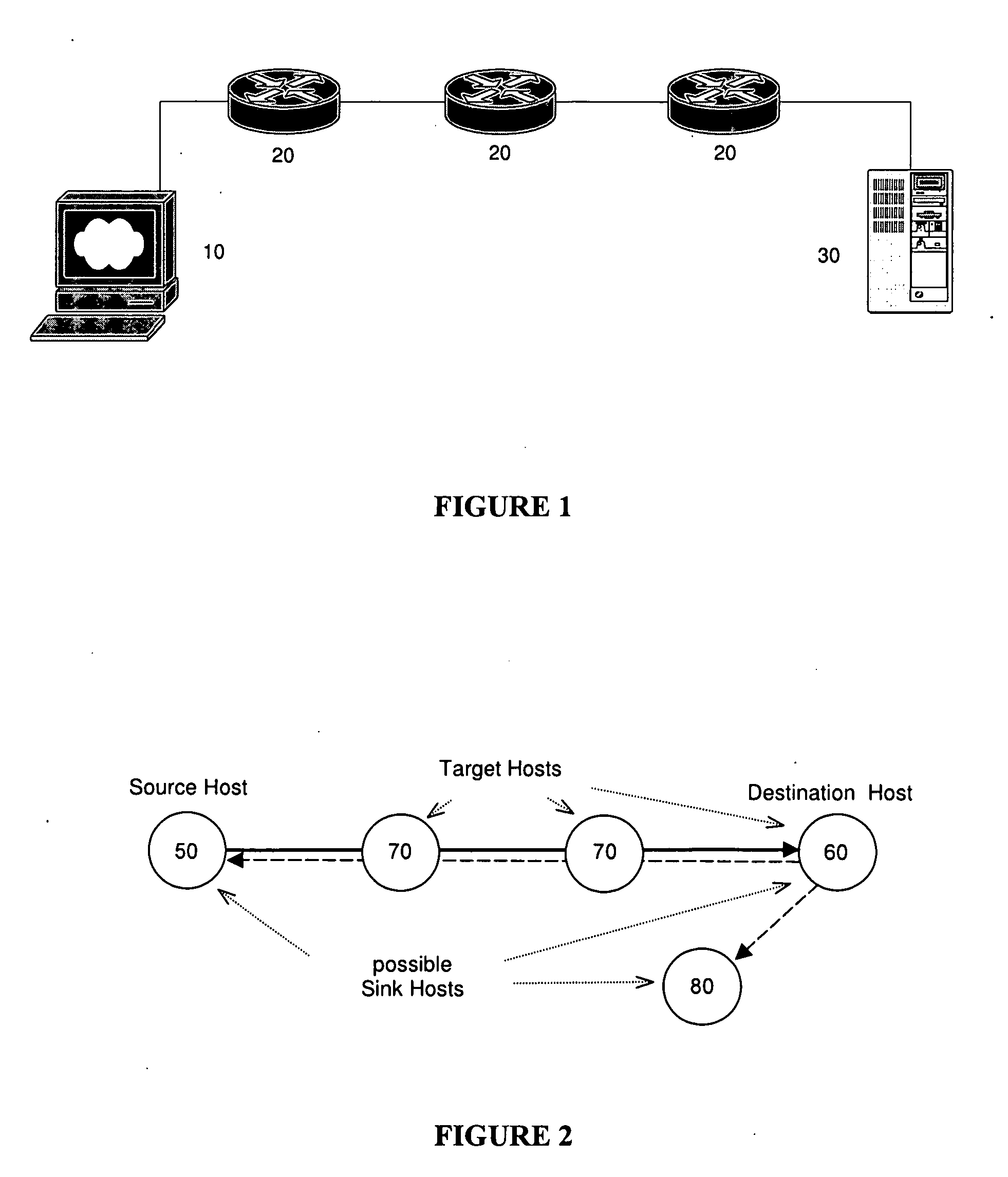
[0030] The term “source host” is used to define the location or node of a network from which transmission of the packets for characterising the network path originate.

[0031] The term “destination host” is used to define the location or node of a network that defines an end-to-end path with regard to a specific source host.

[0032] The term “target host” is used to define the location or node of a network about which characteristics are to be collected. A target host can be intermediate between the source host and the destination host and may alternately be the destination host.

[0033] The term “sink host” is used to define the location or node of a network at which information regarding the status of the transmitted packets is collected. The sink host can be any node within the network, including the source host, destination host, target host or a node that is not along the path being characterised.

[0034] The term “packet” is used to define a piece of information that ...


PUM


Abstract

The present invention provides a method and apparatus for characterising a path between a source host and a destination host, including characterisation of each segment of the network path between the source host and destination host. The present invention comprises a first stage of data collection, wherein sampling of a network path is enabled by means of sending and receiving specific predetermined ordered groups of packets that can vary in size, number and protocol, wherein all packets are sent from the source host and addressed to the destination host. These ordered groups of packets include strategically arranged marker packets and load packets, wherein the load packets are typically expired at a predetermined node between the source host and destination host, and the marker packets complete their journey to the destination. After expiry of the load packets of a particular ordered group of packets, the marker packets associated therewith provide a means for capturing information relating to network characteristics up to the expiry of these load packets. Subsequent analysis of the collected information enables the characterisation of each segment along a network path between the source host and destination host. The present invention can incorporate a further analysis of the collected information performing a correlation between the characteristics of the ordered groups of packets and the collected information, thereby enabling a means for the adjustment of the characteristics of the ordered groups of packets used during sampling that can result in an optimisation of the sampling and characterisation of the network path.

Description

CROSS-REFERENCE TO RELATED APPLICATIONS [0001] This application claims the benefit of U.S. Provisional Application Ser. No. 60 / 541,928, filed Feb. 6, 2004.FIELD OF THE INVENTION [0002] The present invention pertains to the field of networks and in particular to a method and apparatus for evaluating an end-to-end path of a packet-based network. BACKGROUND [0003] In packet-based networks, it is often desired to test communications between two specific nodes on the network. This can generally be affected from a first one of the nodes by requesting the other node to “loop-back” a test packet sent from the first node. The first node, upon receiving back the test packet, can thereby ascertain not only that communication is possible with the other node, but also the round trip time for the packet. Inter-networking protocols such as the ARPA Internet Protocol (IP) may also provide a facility for determining reachability and round trip time by use of a looped-back test packet. Thus, in IP ne...

Claims


Application Information

Patent Timeline
IPC IPC(8): H04L12/24H04L12/26H04L12/28H04L12/56H04L29/06
CPCH04L41/14H04L41/5035H04L43/0858H04L43/0864H04L43/0882H04L69/16H04L43/50H04L47/10H04L47/115H04L47/18H04L47/283H04L43/10H04L43/091
Inventor JORGENSON, LOKINORRIS, ROBERT CHRISTOPHER
Owner APPARENT NETWORKS INC
Learn More