Electric device having charging function

a technology of electric devices and functions, applied in secondary cells, electrographic processes, instruments, etc., can solve problems such as heating, increase costs, user forgetting to arrange the cover, etc., and achieve the effect of preventing a factor affecting energy transmission

Inactive Publication Date: 2005-10-20
FUNAI ELECTRIC CO LTD
View PDF0 Cites 90 Cited by
  • Summary
  • Abstract
  • Description
  • Claims
  • Application Information

AI Technical Summary

Benefits of technology

[0008] An object of the invention is to provide an electric device, which can easily preclude a factor impeding energy transmission in a non-contact manner during charging.

Problems solved by technology

If the foreign material in the space is metal, the metal causes a problem of heating.
However, the above reference has neither disclosed nor suggested countermeasures against such problems.
However, the user may forget about arranging the cover.
This requires a mechanism for such automatic operation, and increases a cost.

Method used


Image

  • Electric device having charging function
  • Electric device having charging function
  • Electric device having charging function

Examples


first embodiment

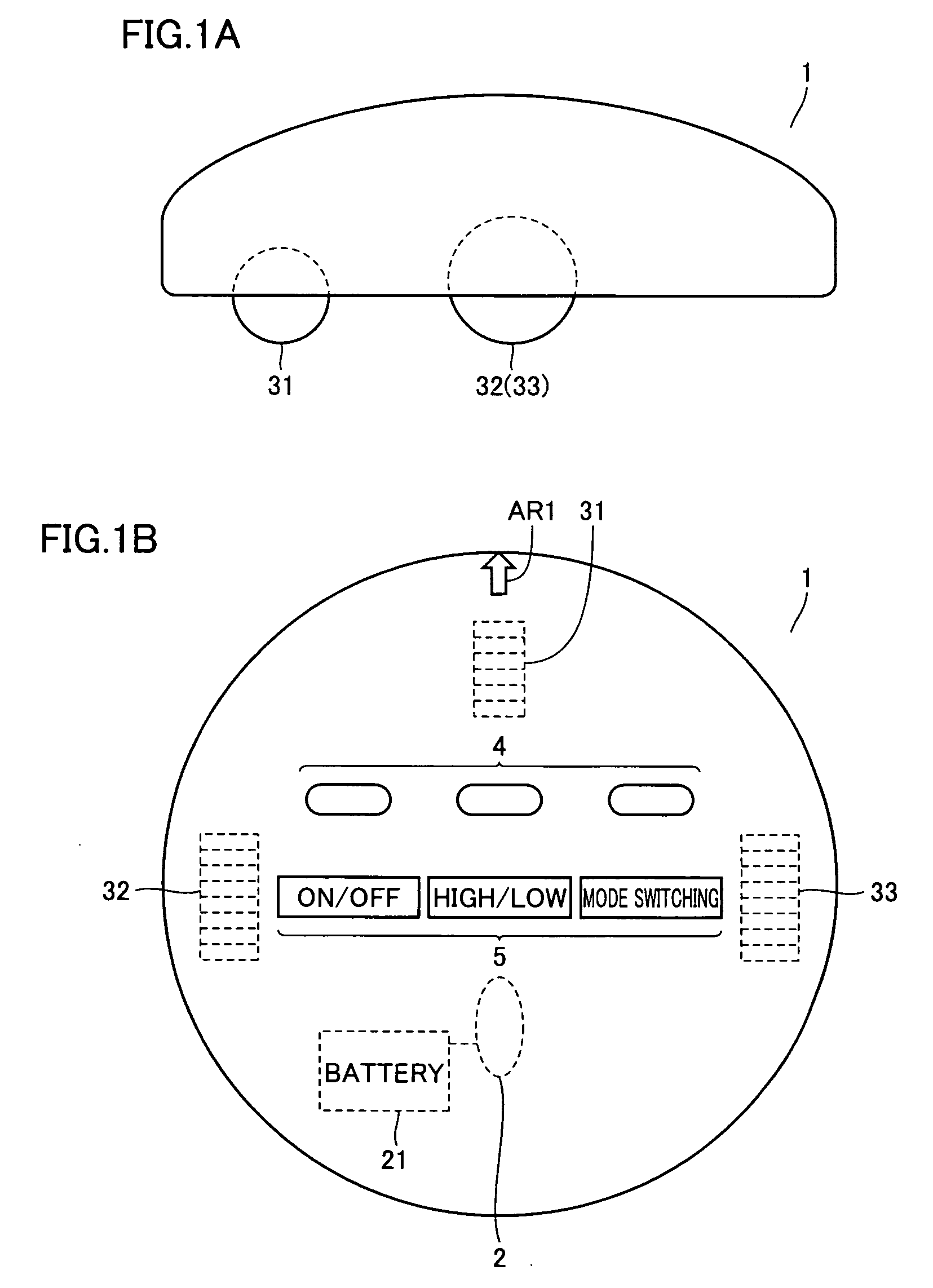
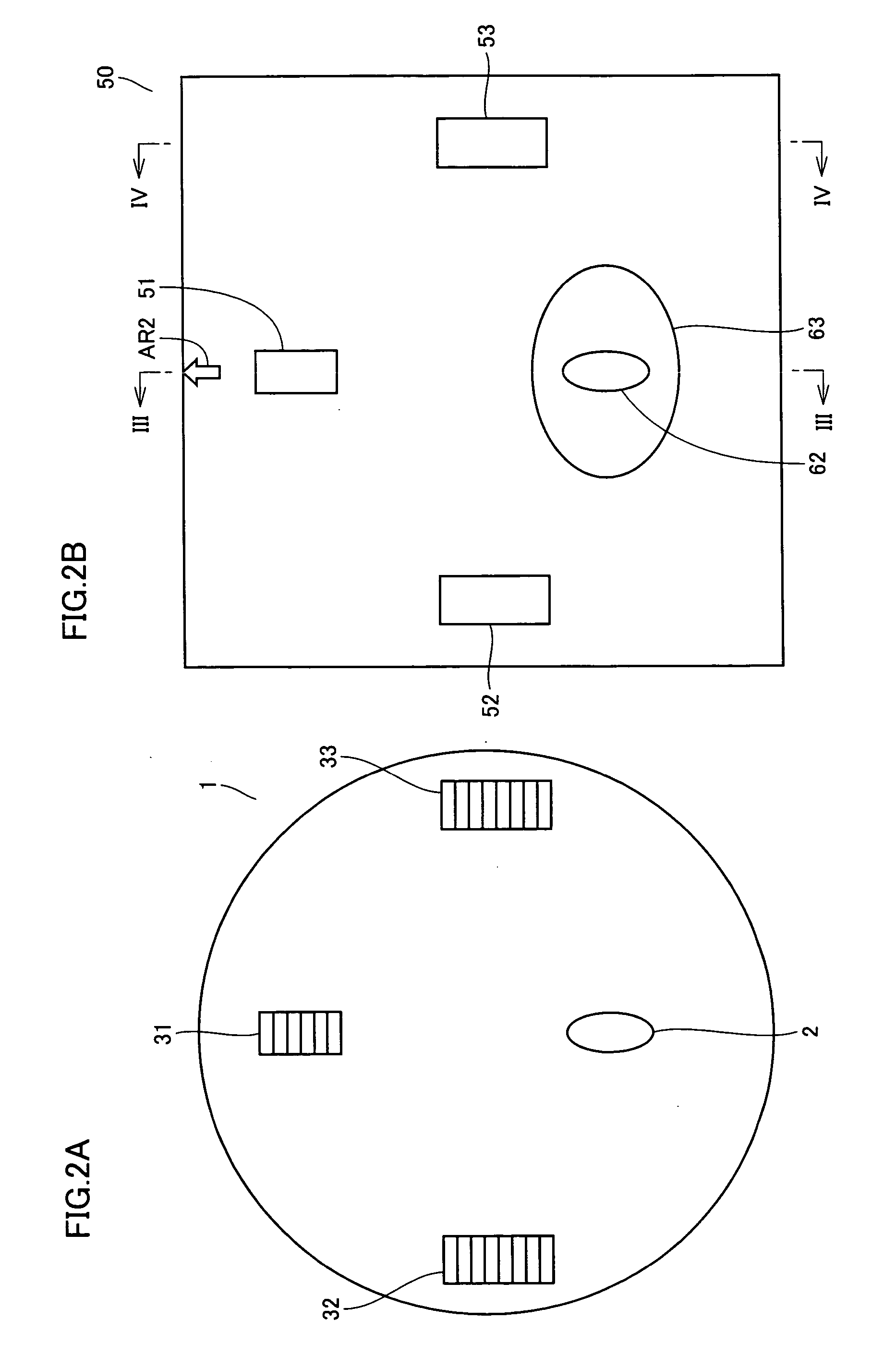
[0034]FIG. 1A shows an outer appearance of a side surface of a mobile work robot 1, and FIG. 1B shows an outer appearance of a top surface of mobile work robot 1. Referring to FIGS. 1A and 1B, mobile work robot 1 includes a front wheel 31 and rear wheels 32 and 33, which are in contact with a floor surface, and is driven to rotate for movement, as well as a LED (Light Emitting Diode) unit 4 arranged on the top surface of a casing of mobile work robot 1 for notifying of an operation mode by light, and a switch unit 5 for manual operation by a user. The casing of mobile work robot 1 is provided at its surface opposed to the floor surface with a charging terminal 2, which is exposed for non-contact charging. The casing of mobile work robot 1 is provided at its top surface with a mark AR1, which is used for positioning when mobile work robot 1 is to be placed on charging unit 1 as will be described later. The operation modes, which are notified by LED unit 4, include an operating mode, ...

second embodiment

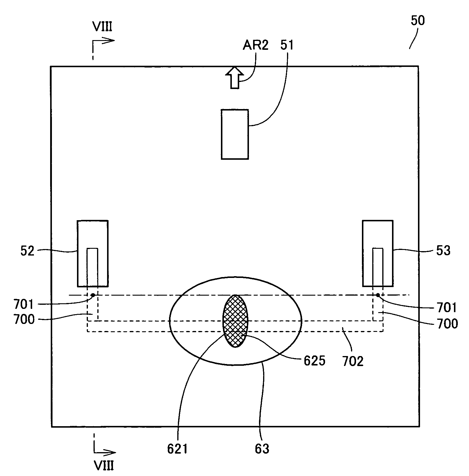
[0046] In FIG. 6, the electrode surface of charging terminal 62 is fixed substantially at the same vertical position or level as the bottom surface of concavity 63, and the electrode surface of charging terminal 2 of mobile work robot 1 projects from the bottom surface of mobile work robot 1 to an extent not impeding the movement. However, a reverse structure may be employed provided that the foregoing gap of the predetermined distance can be kept. The example will now be described with reference to FIGS. 5 and 7 to 10.

[0047]FIG. 5 shows a charging terminal 621, which is employed in place of charging terminal 62 in FIG. 3, and has an electrode surface 625. FIG. 10 shows a state, in which mobile work robot 1 is placed on charging unit 50. In FIG. 10, mobile work robot 1 has a charging terminal 622 in place of charging terminal 2. In a normal state, electrode surface 625 of charging terminal 621 of charging unit 50 is located at the same level are the bottom surface (concave surface)...

third embodiment

[0053] The foregoing structures use concavity 63 for forming the gap, which is used for the charging, and for protecting the electrode from damage. Instead of concavity 63, a nonconductive member 630 (e.g., a rubber wall) hatched in FIGS. 11 and 12 may be arranged to surround a charging terminal 631. Nonconductive member 630 has a ring-like form surrounding charging terminal 631, and is fixed to the top surface of charging unit 50. Since charging terminal 631 is always surrounded by nonconductive member 630, it is possible to prevent damage due to contact with another member. A height of the ring of nonconductive member 630 from the top surface of charging unit 50 is merely required to allow such a state that nonconductive member 630 substantially cuts off the space (gap), which is formed between charging terminal 632 of mobile work robot 1 and charging terminal 631 for magnetic flux transmission, from its external side in the charging operation. Since ring-like nonconductive member...


PUM

PropertyMeasurementUnit
energyaaaaaaaaaa
weightaaaaaaaaaa
poweraaaaaaaaaa

Abstract

For charging in a non-contact manner, a mobile work robot is placed on a charging unit provided with a unit-side terminal providing an energy for charging. The mobile work robot receives an energy for charging the battery from the unit-side terminal via a robot-side terminal. For the charging, the mobile work robot is placed on the charging unit such that a surface provided with the robot-side terminal is opposed to a surface provided with the unit-side terminal. The surface portion provided with the robot-side terminal and the surface portion provided with the unit-side terminal form a protection unit, which is a space for cutting off a region for energy transmission for charging from an external side.

Description

BACKGROUND OF THE INVENTION [0001] 1. Field of the Invention [0002] The present invention relates to an electric device having a charging function, and particularly to an electric device having a function of charging a battery of a target device. [0003] 2. Description of the Background Art [0004] As a kind of electric devices of a rechargeable type, there has been a mobile work robot having functions of automatic moving and working. The mobile work robot has a rechargeable battery, which can be charged by a charging unit independent of the mobile work robot. [0005] The charging unit is connected to a commercial power supply. When the mobile work robot is connected to the charging unit, a power is supplied from the commercial power supply to the mobile work robot to charge the battery. A cleaner employing the above charging method is disclosed, e.g., in Japanese Patent Laying-Open No. 2003-142164. The charging method disclosed in the above reference can charge a battery in a body of ...

Claims


Application Information

Patent Timeline
Patent Type & Authority Applications(United States)
IPC IPC(8): H02J7/00G03G15/08H01M10/44
CPCH02J7/025H02J7/0042H02J50/005H02J7/0044H02J50/10H02J50/80H02J50/90
Inventor TAKENAKA, HIROYUKI
Owner FUNAI ELECTRIC CO LTD
Why Eureka
Try Eureka