
Dual treadmill exercise device having a single rear roller

a technology of rear roller and exercise device, which is applied in the direction of cardiovascular exercise device, gymnastic exercise, sport apparatus, etc., can solve the problem of adding to the manufacturing cost of the exercise devi

Active Publication Date: 2005-10-20
NAUTILUS INC
View PDF23 Cites 76 Cited by
  • Summary
  • Abstract
  • Description
  • Claims
  • Application Information

AI Technical Summary

Benefits of technology

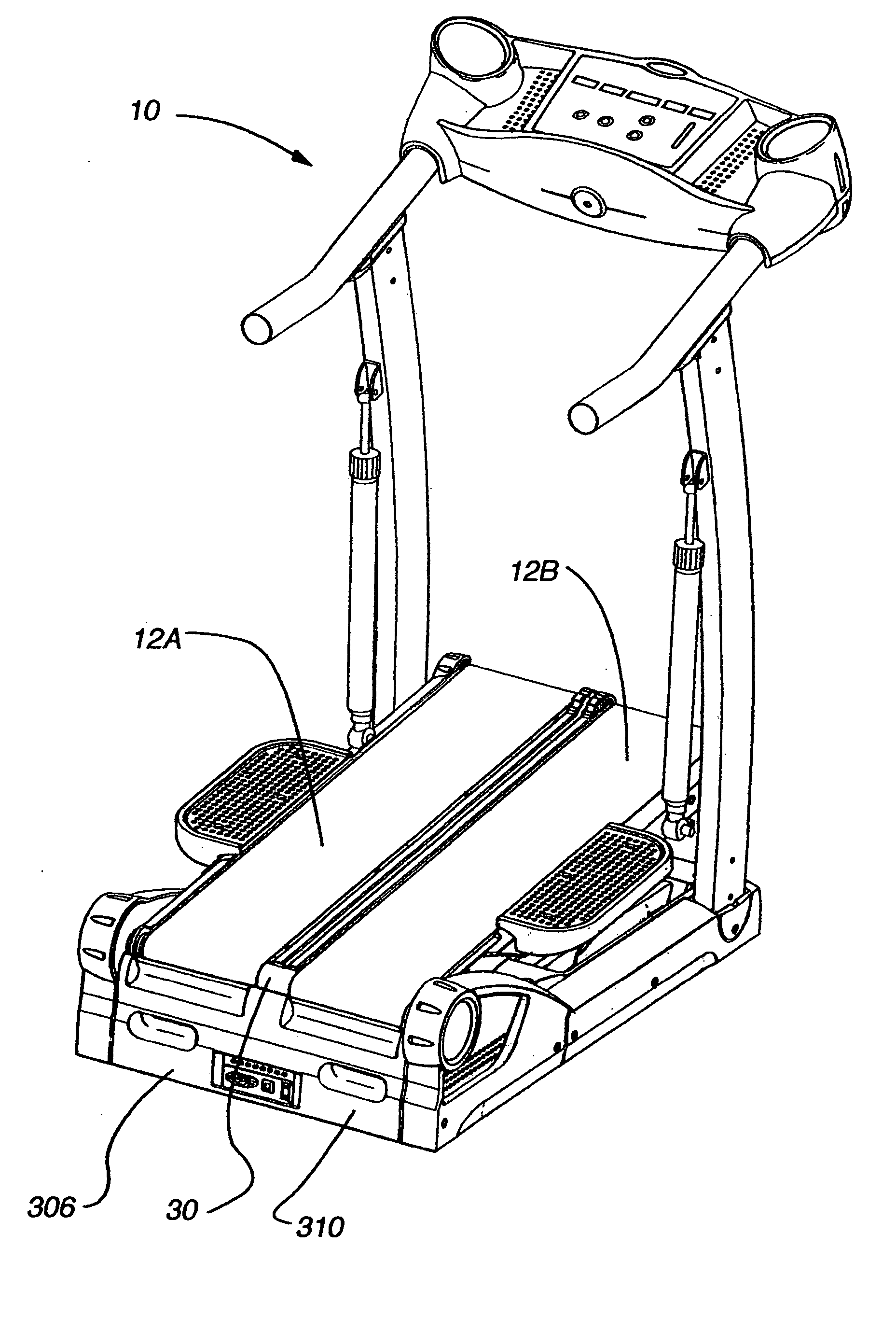
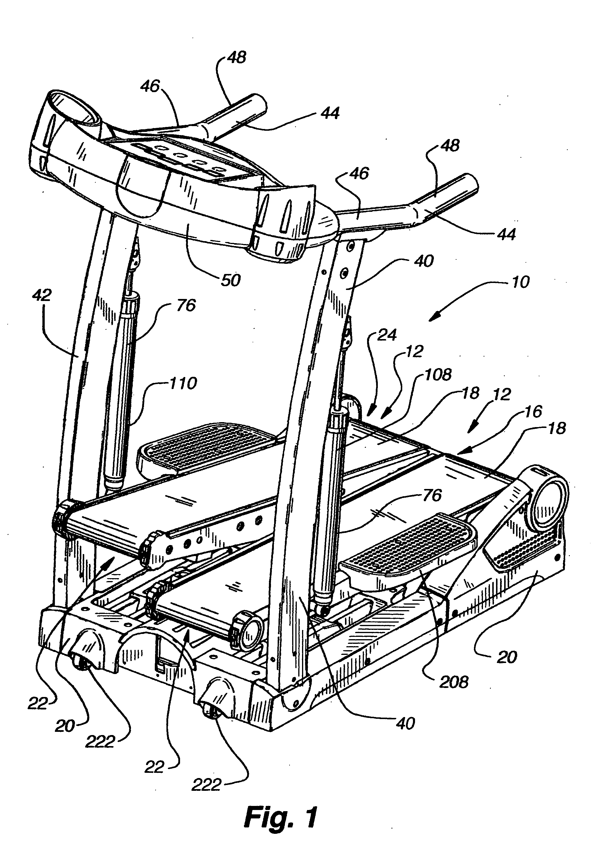
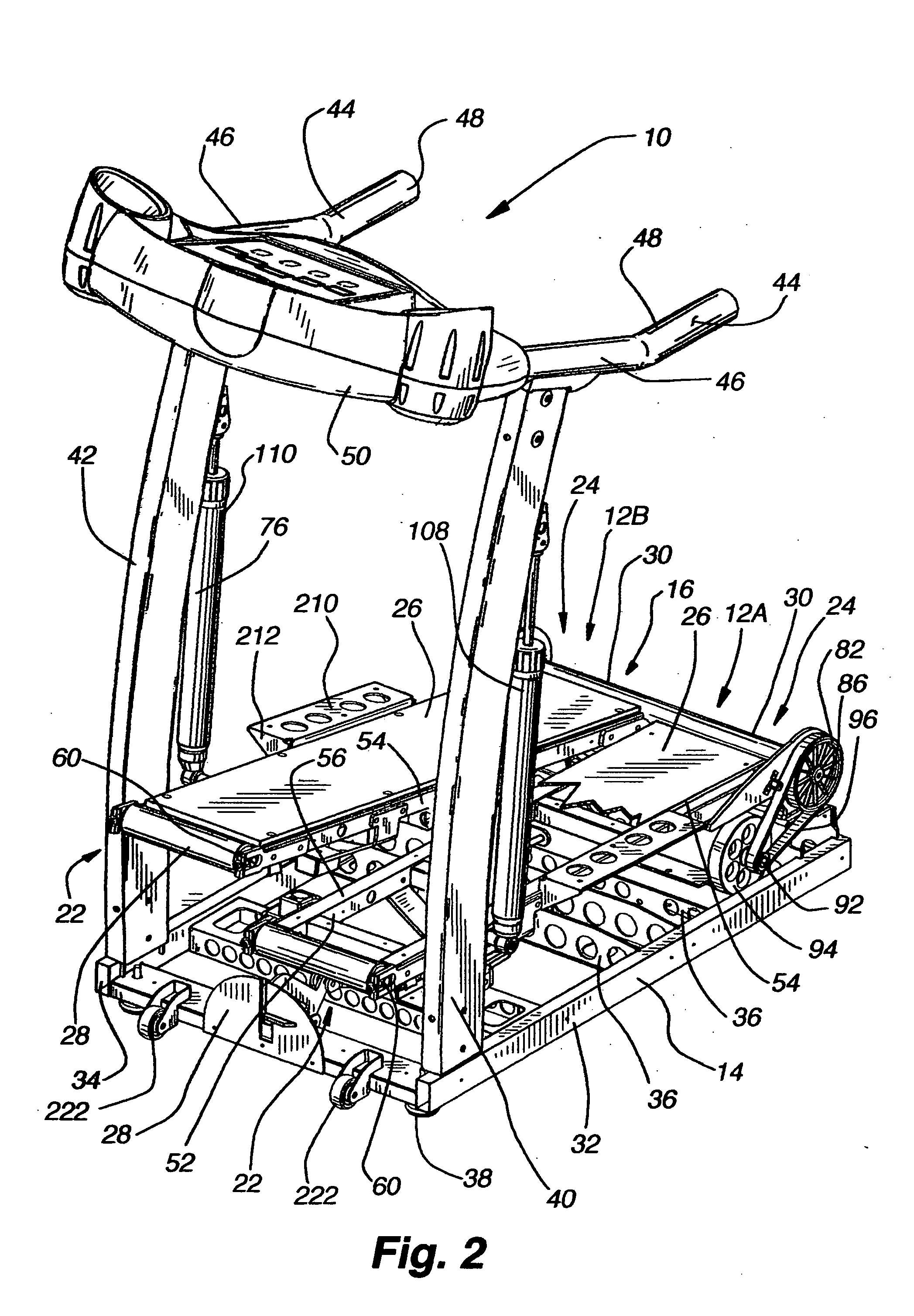
[0017] An exercise device conforming to the present invention generally includes two treadmill-like assemblies (referred to herein as a “treadle” or a “treadle assembly”) pivotally connected with a frame so that the treadles may pivot up and down about an axis. Each treadle includes a tread belt that provides a moving surface like a treadmill. Each tread belt is supported by a front roller and a rear roller, which is common to both treadles. In use, a user will walk, jog, or run on the treadles and the treadles will reciprocate about the treadle pivot axis. The treadles are interconnected to provide an alternating upward and downward movement. Opposing end portions of the rear roller are rotatably supported at the rear end of the frame. Outer sides of rear end portions of the treadles are rotatably supported by the outer end portions of the rear roller, and inner sides of rear end portions of the treadles are coupled with the frame through an inner support structure that defines a virtual pivot. The inner support structure allows each treadle to be positioned more closely to one another along the inner sides than a comparable exercise device having two separate rear rollers. Using a single rear roller also eliminates the need for two inner rear roller support structures and associated bearings.

Problems solved by technology

This space requires a user of the exercise device to keep his feet a particular distance apart when using the exercise device in order to avoid stepping on the inside edge of the treadle during use, which can be an inconvenience.
The need for two inner support structures and associated bearings also add to the manufacturing costs of the exercise device.

Method used


Image

  • Dual treadmill exercise device having a single rear roller
  • Dual treadmill exercise device having a single rear roller
  • Dual treadmill exercise device having a single rear roller

Examples


Embodiment Construction

[0074] An exercise device 10 conforming to the present invention may be configured to provide a user with a walking-type exercise, a stepping-type exercise or a climbing-like exercise that is a combination of both walking and stepping. The exercise device generally includes two treadmill-like assemblies 12 (referred to herein as a “treadle” or a “treadle assembly”) pivotally connected with a frame 14 so that the treadles may pivot up and down about an axis 16. The axis may be a physical axis (axle) or may be a virtual axis defined by assemblies of components that pivotally support each treadle. In one implementation, each treadle includes a tread belt 18 that provides a moving surface like a treadmill. Each tread belt is supported by a front roller and a rear roller. The rear roller is common to both treadles. Further, the rear roller may be supported on the frame or treadle, and may share an axis of rotation with the treadles or may have a unique axis of rotation forward, rearward,...


PUM


Abstract

The present invention provides an exercise device that generally includes two treadles pivotally connected with a frame so that the treadles may pivot up and down about an axis. Each treadle includes a tread belt that provides a moving surface like a treadmill. Each tread belt is supported by a front roller and a rear roller, which is common to both treadles. The treadles are interconnected to provide an alternating upward and downward movement relative to each other. Opposing end portions of the rear roller are rotatably supported at the rear end of the frame. Outer sides of rear end portions of the treadles are rotatably supported by the outer end portions of the rear roller, and inner sides of rear end portions of the treadles are coupled with the frame through an inner support structure that defines a virtual pivot.

Description

CROSS-REFERENCE TO RELATED APPLICATIONS [0001] The present application is a non-provisional utility application claiming priority to U.S. Provisional Application No. 60 / 548,811, titled “Dual Treadmill Exercise Device Having a Single Rear Roller” and filed on Feb. 26, 2004, U.S. Provisional Patent Application No. 60 / 548,265 titled “Exercise Device with Treadles (Commercial)” filed on Feb. 26, 2004, U.S. Provisional Patent Application No. 60 / 548,786 titled “Control System and Method for an Exercise Apparatus” filed on Feb. 26, 2004, and U.S. Provisional Patent Application No. 60 / 548,787 titled “Hydraulic Resistance, Arm Exercise, and Non-Motorized Dual Deck Treadmills” filed on Feb. 26, 2004, which are all hereby incorporated herein by reference. [0002] The present application is a continuation-in-part of U.S. application Ser. No. 10 / 789,182, titled “Dual Deck Exercise Device” and filed on Feb. 26, 2004; the present application is a continuation-in-part of U.S. application Ser. No. 10...

Claims


Application Information

Patent Timeline
IPC IPC(8): A63B22/02A63B22/04A63B23/04
CPCA63B21/0083A63B21/225A63B22/0056A63B22/02A63B2071/0063A63B22/0285A63B2022/0214A63B2022/0292A63B22/0235A63B22/0214A63B22/0292
Inventor SMITH, BRADLEY J.TREVINO, RICHARD W.CRAWFORD, DOUGLAS A.
Owner NAUTILUS INC
Learn More