Multi-network monitoring architecture

a monitoring architecture and network technology, applied in the field of computer networks, can solve the problems of inability to achieve any kind of operation, inability to efficiently execute business functions, and inability to achieve any operation,

Inactive Publication Date: 2005-10-20
N ABLE TECH INT
View PDF25 Cites 209 Cited by
  • Summary
  • Abstract
  • Description
  • Claims
  • Application Information

AI Technical Summary

Benefits of technology

[0016] In yet another embodiment of the first aspect, the remote central management unit includes a data management system for extracting the performance data from the message and for providing an alert in response to the failure threshold being reached, a data repository for storing the performance data received by the data management system and the predefined rule, a notification system for generating a notification message in response to the alert, and a user interface for configuring the predefined rule and the agent system configuration data, the data management system encapsulating and transmitting the agent system configuration data to the agent system.
[0017] In a second aspect, the present invention provides a method of monitoring a computer network from a remote central management unit, the computer network having an agent system for collecting performance data thereof, and the remote central management unit having rules with corresponding failure thresholds for application to the performance da

Problems solved by technology

Consequently, if the technology fails, the business functions may not be executed efficiently, and in a worst case scenario, they may not be executed at all.
Network failure mechanisms are well known to those of skill in the art, and can be caused by malicious “spam” attacks, hardware failure or software failure, for example.
The financial resources required to support an IT group and the required tools in large enterprise, are considerable and unattainable by the small to medium size business (SMB).
Unfortunately there are few technology solutions designed to support the IT service provider, and no solutions that are offered as a stand-alone product (as opposed to a subscribed service).
Providing a centralized monitoring solution for multiple client networks presents a number of significant technical challenges for most small businesses: Most use low-end commodity hardware which is neither manageable nor robust; Small businesses typically rely on Internet connect

Method used


Image

  • Multi-network monitoring architecture
  • Multi-network monitoring architecture
  • Multi-network monitoring architecture

Examples


Embodiment Construction

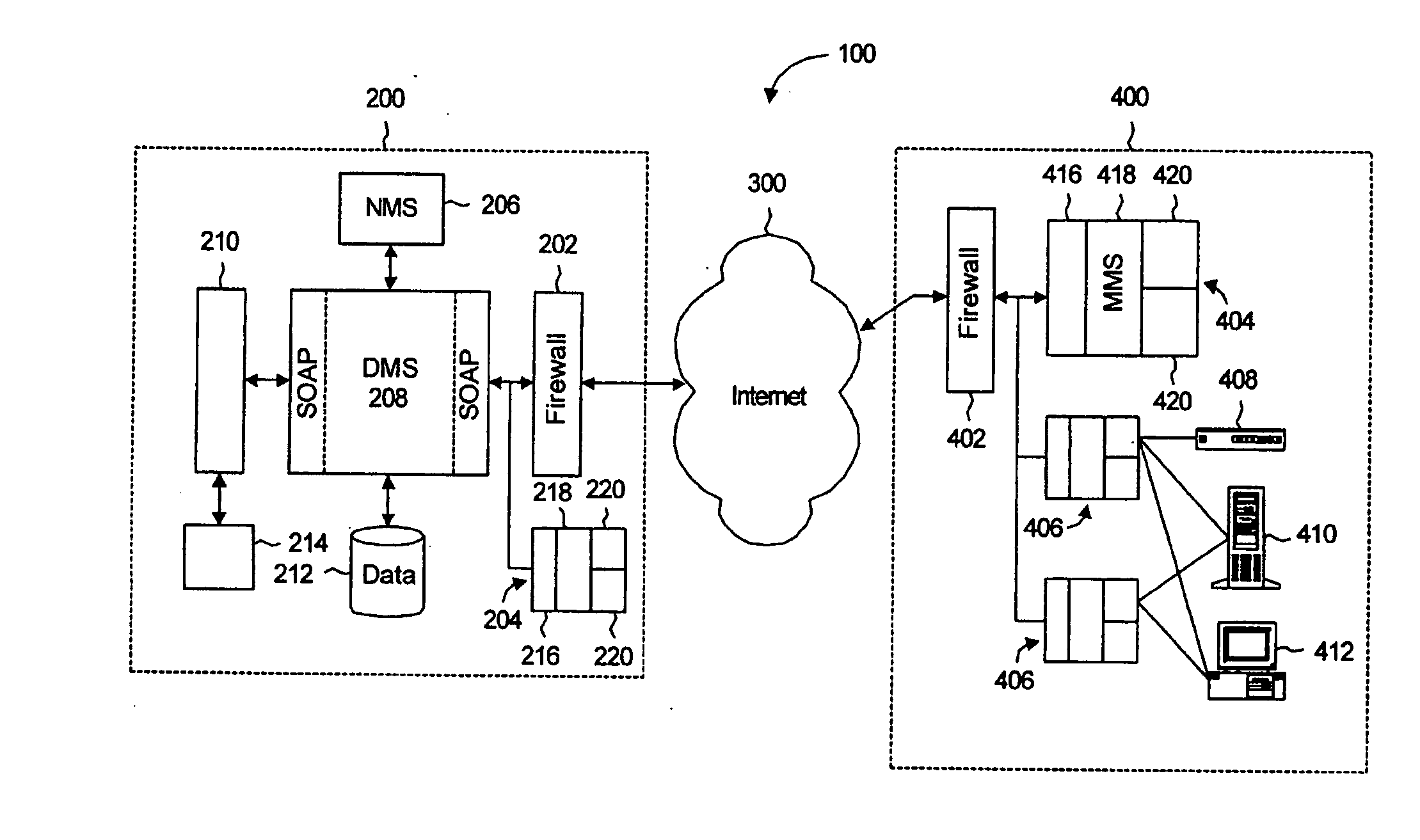
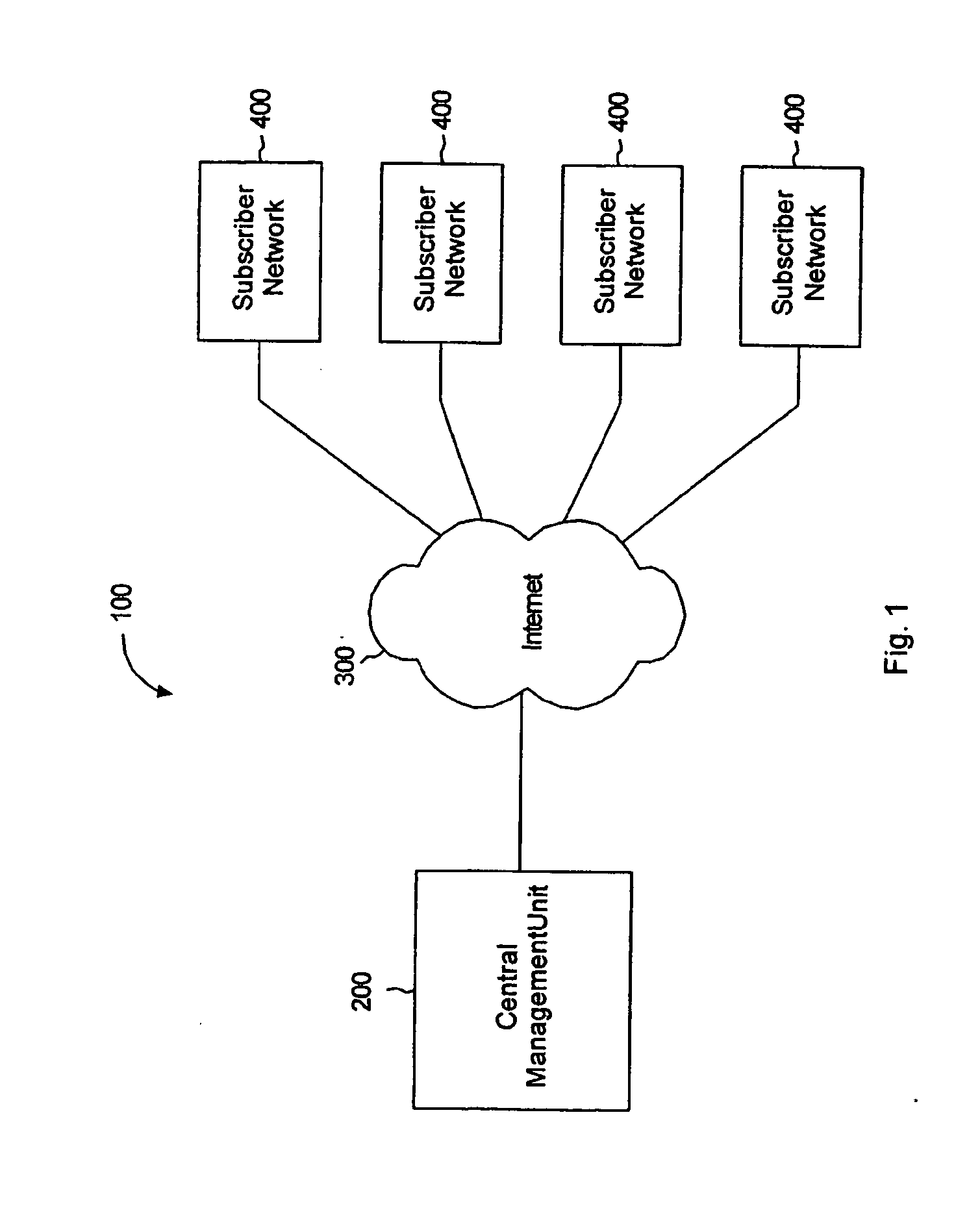
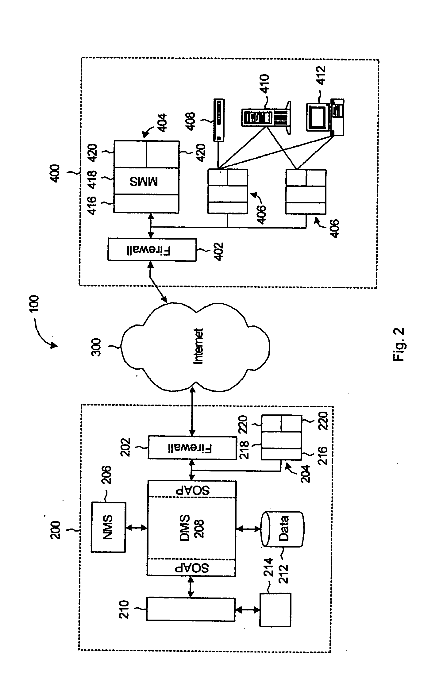
[0025] A centralized network monitoring architecture for multiple computer network systems is disclosed. In particular, the network monitoring architecture includes an agent system installed within each computer network and a remote. central management unit in communication with the agent system of each computer network. The agent system collects data from key network devices that reside on the computer network, and sends the collected data to the remote central management unit as messages through a public communications network, such as the Internet or any suitable publicly available network. The data from the computer networks are processed at the remote central management unit to determine imminent or actual failure of the monitored network devices by applying rules with corresponding failure thresholds. The appropriate technicians can then be immediately notified by the central management unit through automatically generated messages. Because the data processing system, hardware...


PUM


Abstract

A network monitoring architecture for multiple computer network systems is disclosed. In particular, the network monitoring architecture includes an agent system installed within each computer network and a remote central management unit in communication with the agent system of each computer network. The agent systems collect data from key network devices that reside on the corresponding computer network, and send the collected data to the remote central management unit as a message through the Internet. The data from the computer networks are processed at the remote central management unit to determine imminent or actual failure of the monitored network devices. The appropriate technicians can be immediately notified by the central management unit through automatically generated messages.

Description

FIELD OF THE INVENTION [0001] The present invention relates to computer networks. In particular, the present invention relates to a network monitoring system for maintaining network performance. BACKGROUND OF THE INVENTION [0002] Technology has advanced to the state where it is a key enabler for business objectives, effectively creating an important reliance upon technologies such as email, web, and e-commerce for example. Consequently, if the technology fails, the business functions may not be executed efficiently, and in a worst case scenario, they may not be executed at all. Network failure mechanisms are well known to those of skill in the art, and can be caused by malicious “spam” attacks, hardware failure or software failure, for example. [0003] Large companies mitigate these risks through internal information technology (IT) groups, with budgets to support sophisticated systems monitoring solutions. The financial resources required to support an IT group and the required tool...

Claims


Application Information

Patent Timeline
IPC IPC(8): H04L12/24H04L12/26
CPCH04L12/2602H04L41/046H04L41/0681H04L43/16H04L43/0811H04L43/0817H04L43/12H04L43/00
Inventor RACKUS, PHILCARTER, CLAUDIUFAUTEUX, JEANGILBERT, ADRIAN
Owner N ABLE TECH INT
Why Eureka
Try Eureka