
System and method for multimedia viewership surveying

a viewership survey and multimedia technology, applied in the field of multimedia viewership surveying, can solve the problems of service provider loss of revenue, increase in the amount of bandwidth required for transmission, and waste of vast majority of bandwidth, so as to reduce the total bandwidth transmitted, increase the transmission multimedia channel quality, and increase the effect of bandwidth transmitted

Active Publication Date: 2005-10-20
AVAGO TECH INT SALES PTE LTD
View PDF15 Cites 123 Cited by
  • Summary
  • Abstract
  • Description
  • Claims
  • Application Information

AI Technical Summary

Benefits of technology

[0058] In an embodiment according to the present invention, the method may further comprise reducing total bandwidth transmitted to each subscriber by transmitting multimedia channel information selected by each subscriber independently.
[0059] In an embodiment according to the present invention, the method may further comprise increasing transmitted multimedia channel quality by increasing bandwidth transmitted for each requested multimedia channel selected by each subscriber independently.

Problems solved by technology

Because all channels are being transmitted together to each end-user location, end-users may be able to illegally decode unsubscribed channels for viewing causing the service provider to lose revenue.
Additionally, as the number of channels being transmitted increases, the amount of bandwidth required for transmission increases.
The vast majority of bandwidth, however, is wasted.
The result is that in many instances, as much as or more than 99% of the bandwidth (channels) being transmitted is wasted and not viewed.
Further, there is a significant waste of power because of transmission of all the channels all the time.
Further, there is no definitive way to retrieve channel viewership information in current cable TV systems.

Method used


Image

  • System and method for multimedia viewership surveying
  • System and method for multimedia viewership surveying
  • System and method for multimedia viewership surveying

Examples


Embodiment Construction

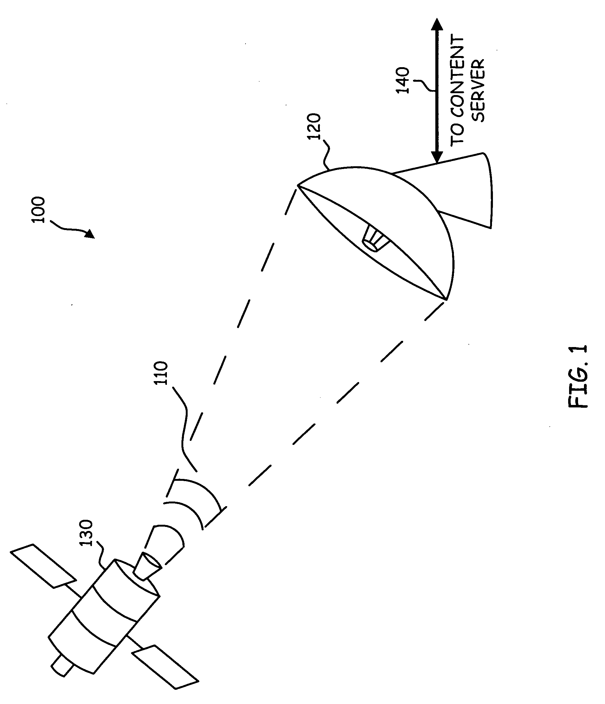
[0080]FIG. 1 is a perspective diagram 100 illustrating a satellite transmission / reception system in accordance with an embodiment of the present invention. In FIG. 1, a satellite 130 is illustrated transmitting multimedia information 110 to a satellite receiver 120. The satellite receiver 120 may be located proximate a service provider location. The satellite receiver 120 may comprise of a receiving antenna and a tuner.

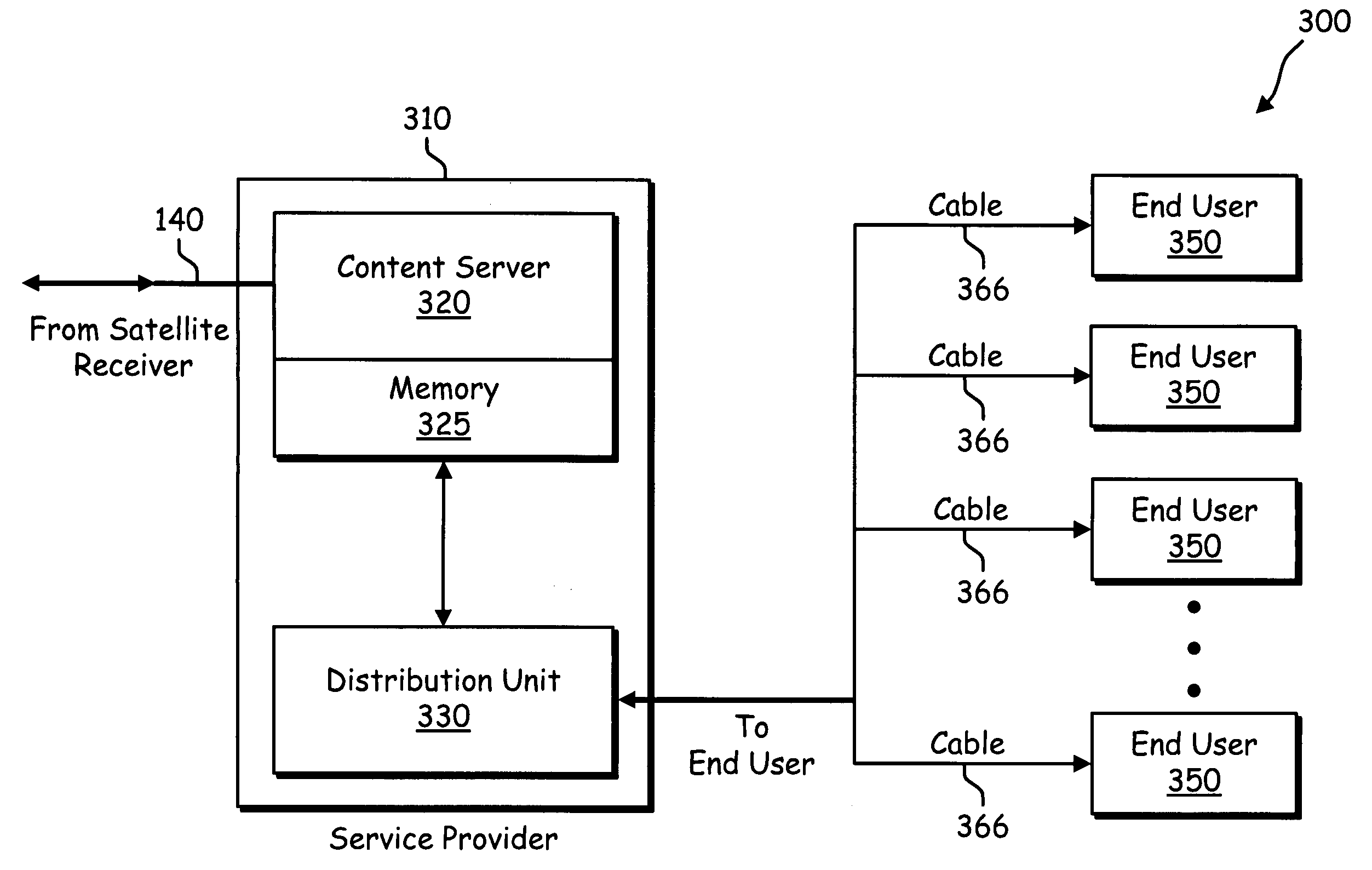
[0081] The service provider may comprise a cable television service provider, an Internet service provider, a radio service provider, and other multimedia service providers. The multimedia information received at the satellite receiver 120 may be conveyed to the service provider location via transmission cable 140. The multimedia information received at the satellite receiver 120 may also be conveyed to the service provider location via an optical fiber or wirelessly.

[0082] The satellite transmission / reception system illustrated in FIG. 1 may comprise a plurality of...


PUM


Abstract

Disclosed herein is a method and system for multimedia viewership surveying of an end-user's set-top-box (STB) The multimedia information may be received from at least one satellite via a satellite receiver. The satellite receiver may convey the multimedia information to a service provider location. At the service provider location, a content server may receive a request for transmission of multimedia information. The request may be validated to determine whether the request is authorized. The method may also include monitoring channel requests, and channel viewing times. The method may also include recording and / or logging the channel requests and information associated with the requested program in a user log. The user log may be evaluated to facilitate targeted marketing of end-user subscribers based upon demonstrated television viewing habits.

Description

RELATED APPLICATIONS [0001] [Not Applicable]FEDERALLY SPONSORED RESEARCH OR DEVELOPMENT [0002] [Not Applicable]MICROFICHE / COPYRIGHT REFERENCE [0003] [Not Applicable]BACKGROUND OF THE INVENTION [0004] Cable television (TV) has become a widely subscribed to commodity. Cable TV typically comprises a plurality of audio / video (A / V) transmissions accumulated in a central office, for example. The A / V transmissions may be accumulated in a content server, for example. [0005] The content server is an information storage unit adapted to collect, accumulate, package, disseminate, and broadcast multimedia data to clients at various locations remote from the central office. [0006] A common central content server may be located in a central office of a service provider. The content server may comprise a plurality of content servers residing in multiple geographic locations. [0007] Typically, cable TV transmissions (channels) are distributed to end-users over cables, thus cable TV. The channels may...

Claims


Application Information

Patent Timeline
IPC IPC(8): G06F3/00H04N7/16
CPCH04N21/25875H04N21/25883H04N21/44204H04N21/6143H04N21/4667H04N21/6118H04N21/6131H04N21/44222
Inventor RELAN, SANDEEPMISHRA, BRAJABANDHUKHARE, RAJENDRA
Owner AVAGO TECH INT SALES PTE LTD
Learn More