Airfoil box and associated method

a technology of airfoil and associated methods, which is applied in the field of airfoil box manufacturing, can solve the problems of time-consuming process for the formation and fastening of the various components, and the total weight of the final wing, so as to facilitate the automatic manufacture of the box and reduce the weight of the box

Inactive Publication Date: 2005-10-27
THE BOEING CO
View PDF5 Cites 83 Cited by
  • Summary
  • Abstract
  • Description
  • Claims
  • Application Information

AI Technical Summary

Benefits of technology

[0006] The present invention meets these and other needs by providing an airfoil box and associated method. The airfoil box is formed of two or more half-shell structures. Each half-shell structure is an integral or unitary member that includes at least a portion of the outer skin o

Problems solved by technology

Often, at least some of the joints must be formed manually, for example, where the joints are formed at internal locations in the wing that are difficult to access using conventional automated joining machines.
The formation and fasten

Method used


Image

  • Airfoil box and associated method
  • Airfoil box and associated method
  • Airfoil box and associated method

Examples


Embodiment Construction

[0025] The present invention now will be described more fully hereinafter with reference to the accompanying drawings, in which some, but not all embodiments of the invention are shown. Indeed, the invention may be embodied in many different forms and should not be construed as limited to the embodiments set forth herein; rather, these embodiments are provided so that this disclosure will satisfy applicable legal requirements. Like numbers refer to like elements throughout.

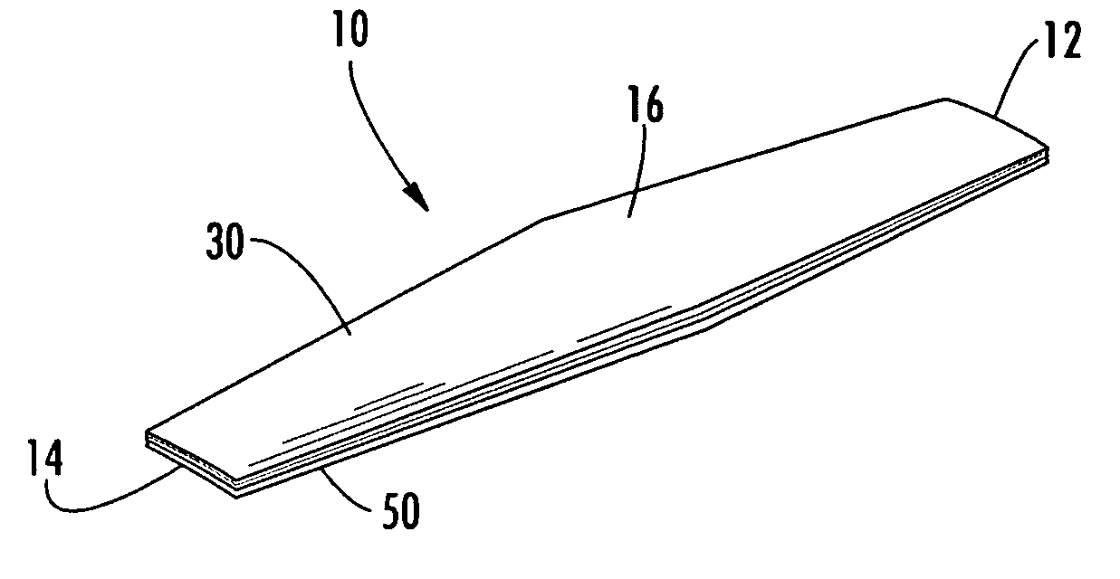
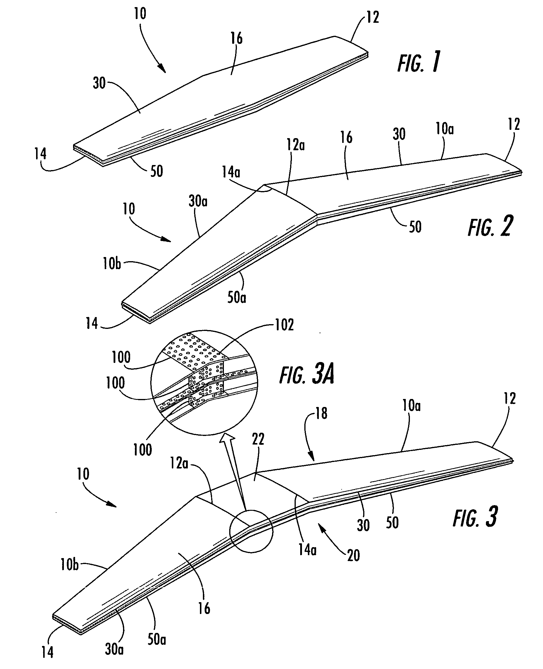
[0026] Referring now to the figures and, in particular, to FIGS. 1-3, there are shown airfoil boxes 10 according to three embodiments of the present invention. Each of the airfoil boxes 10 extends between first and second longitudinal ends 12, 14 and defines an outer skin surface 16 therebetween. The skin surface 16 defines a cross-sectional shape that is structured so that the box 10 can be used to control stability, direction, lift, and / or thrust. For example, the airfoil boxes 10 can be used as wings of an air...


PUM


Abstract

An airfoil box and associated method are provided. The airfoil box includes two or more half-shell structures. Each half-shell structure is an integral or unitary member that includes at least a portion of the outer skin of the airfoil as well as stiffener members and connection members. For example, the half-shell structures can be integrally formed of composite materials. The half-shell structures can be assembled by connecting the connection members with fasteners such as rivets to form the airfoil box.

Description

BACKGROUND OF THE INVENTION [0001] 1) Field of the Invention [0002] The present invention relates to the manufacture of airfoils and, more particularly, to an airfoil box formed of multiple unitary partial-shell structures. [0003] 2) Description of Related Art [0004] Certain structural parts have conventionally been manufactured by joining a number of preformed structural members. For example, in the aircraft industry, wings are often manufactured by separately forming, and then joining, one or more skins, stringers, ribs, bulkheads, and spars. The skins, which are typically large laminar members, form the outer contoured airfoil of the wing, and the stringers, ribs, bulkheads, and spars provide a stiff internal framework that supports the skins. The various members are joined by drilling holes through adjacent members and installing rivets or other fasteners in the holes. According to this conventional method, each wing includes many joined components, and each component must be jo...

Claims


Application Information

Patent Timeline
IPC IPC(8): B64C1/00B64C3/00
CPCB64C3/18B64C3/00B64F5/0009B64F5/10
Inventor SARH, BRANKO
Owner THE BOEING CO
Why Eureka
Try Eureka