
Method and apparatus for countering mold deflection and misalignment using active material elements

a technology of active material elements and countering molds, applied in the direction of manufacturing tools, electrical/magnetically converting sensor outputs, and mechanically converting sensor outputs, etc., can solve the problem of not being able to disclose the actual measurement and then correct the shifting, and achieve the effect of effective and efficient means of detecting

Inactive Publication Date: 2005-10-27
HUSKY INJECTION MOLDING SYST LTD
View PDF39 Cites 42 Cited by
  • Summary
  • Abstract
  • Description
  • Claims
  • Application Information

AI Technical Summary

Benefits of technology

[0008] It is an advantage of the present invention to provide injection molding machine apparatus and method to overcome the problems noted above, and to provide an effective, efficient means for detecting and / or correcting deflection and misalignment in a mold provided in an injection molding machine.
[0009] According to a first aspect of the present invention, structure and / or function are provided for an injection mold having a core and a core plate. An active material sensor is configured to be disposed between the core and the core plate and configured to sense a force between the core and the core plate and to generate corresponding sense signals. Wiring structure is coupled, in use, to the active material sensor and configured to carry the sense signals.
[0010] According to a second aspect of the present invention, structure and / or function are provided for a control apparatus for an injection mold having a first surface and a second surface. An active material sensor is configured to be disposed between the first surface and the second surface of the injection molding machine, for sensing a compressive force between the first surface and the second surface and generating a corresponding sense signal. Transmission structure is configured to transmit, in use, the sense signal from the active material sensor.
[0011] According to a third aspect of the present invention, structure and / or steps are provided for controlling deflection between first and second surfaces of an injection molding machine. A piezoceramic actuator is configured to be disposed between the first and second surfaces of the injection molding machine, for receiving an actuation signal, and for generating an expansive force between the first and second surfaces. Transmission structure is configured to transmit an actuation signal to the piezoceramic actuator.

Problems solved by technology

While Brown discloses a means to improve the alignment between core and cavity and to reduce the effects of core shift (“offset”), there is no disclosure of actually measuring and then correcting such shifting, in a proactive manner.

Method used


Image

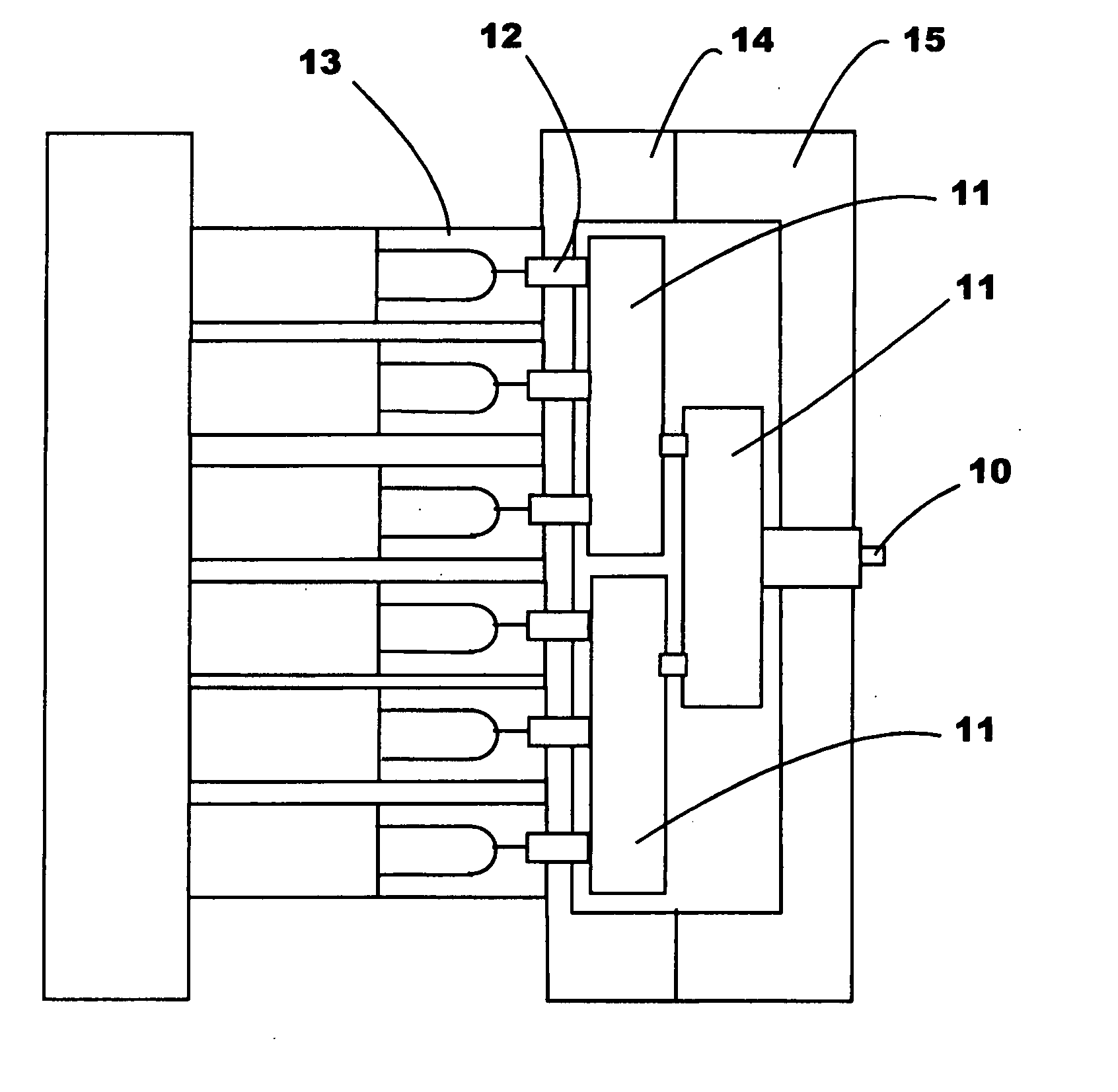
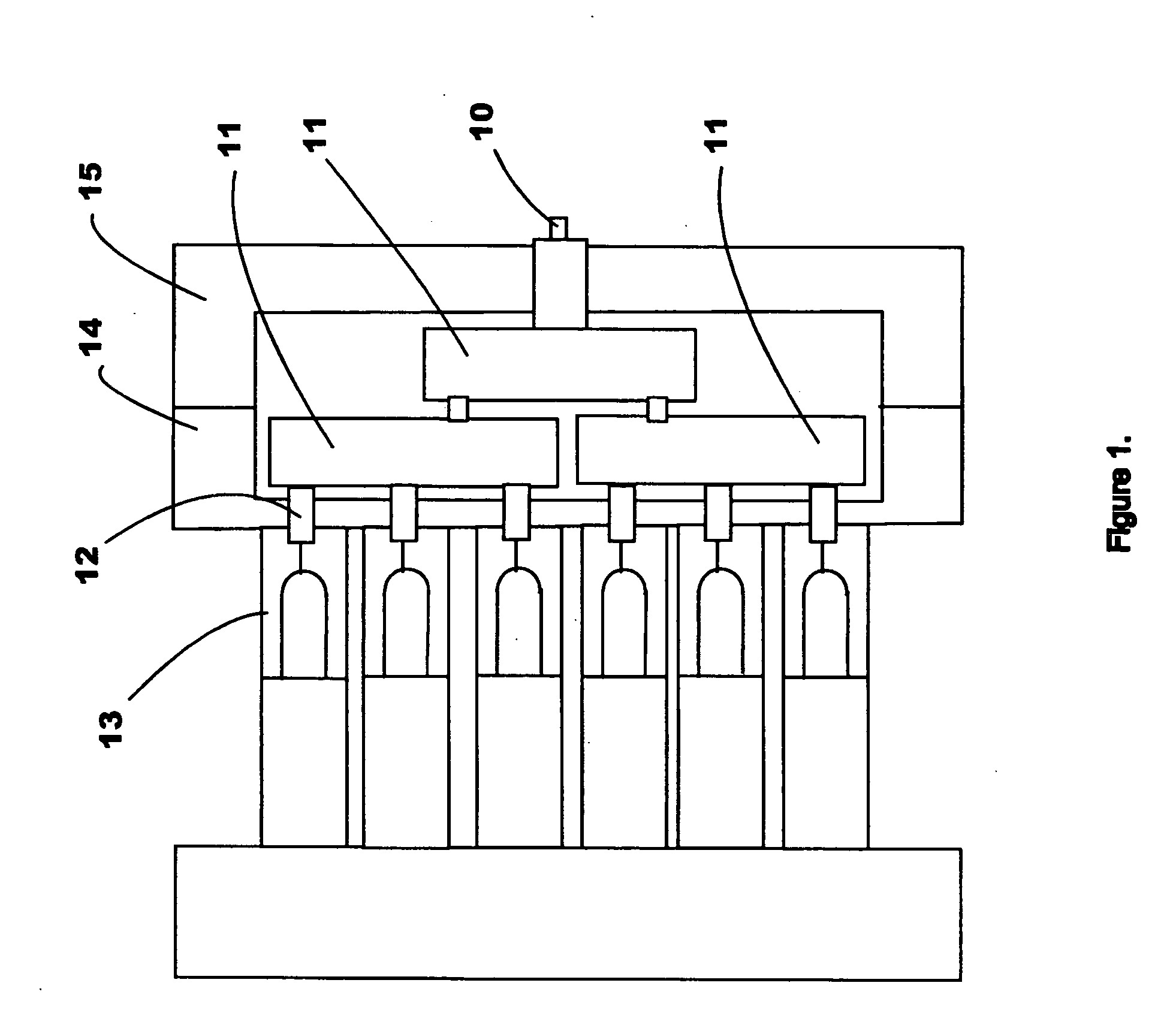
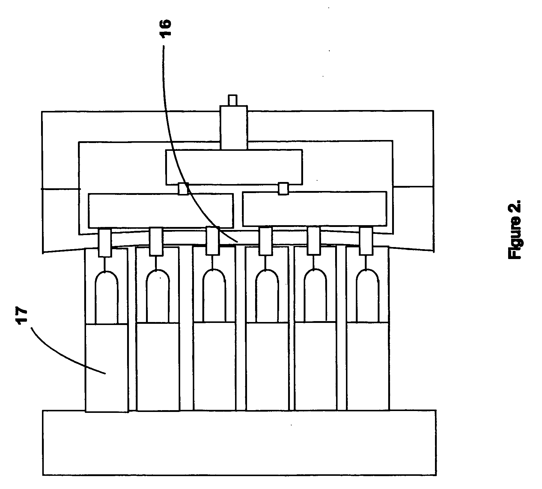
  • Method and apparatus for countering mold deflection and misalignment using active material elements
  • Method and apparatus for countering mold deflection and misalignment using active material elements
  • Method and apparatus for countering mold deflection and misalignment using active material elements

Examples


first embodiment

2. The Structure of the First Embodiment

[0023] The first preferred embodiment of the present invention is shown in FIG. 3, which depicts an injection molding machine preform molding stack 101 of the core lock style. The stack comprises a gate insert 120, a cavity 121, neck ring halves 122a and 122b, a core 123, and a core sleeve 124. The core sleeve 124 has a flange 125 through which several spring loaded fasteners (including, e.g., a bolt 126, a washer 127, and a spring washer (Belleville) 128) are used to fasten the sleeve to the core plate 129. The core 123 has an annular channel 130 in its base to accept an annular shaped piezoceramic element 131. The core plate 129 has a wire groove 132 to accept wiring connections 133 to the element 131. The piezoceramic element 131 may also be driven by wireless means (not shown).

[0024] The piezo-electric element 131 may comprise a piezo-electric sensor or a piezo-electric actuator (or a combination of both), and may, for example, comprise a...

second embodiment

4. The Structure of the Second Embodiment

[0033]FIG. 4 shows an alternate preform molding stack 102 for a cavity lock style stack. The stack comprises a gate insert 150, a cavity 151, neck ring halves 152a and 152b, and a core 153. The core 153 has a flange 155 through which several spring loaded fasteners (e.g., a bolt 156, a washer 157, and a spring washer (Belleville) 158) are used to fasten the core 153 to the core plate 159. The core 153 has an annular channel 160 in its base to accept an annular shaped piezoceramic insert 161. The core plate 159 has a wire groove 162 to accept wiring connections 163 to the element 161, and the wiring connections 163 may optionally be connected to a controller 171. There is a similar assembly gap 170, typically less than 0.1 mm.

[0034] Optionally, one or more separate piezoceramic sensors may be provided to detect pressure caused by positional changes within the mold. These sensors may also be connected by conduits 163 to the controller 171. The...

third embodiment

6. The Structure of the Third Embodiment

[0037]FIG. 5 illustrates one problem that can occur when molding thinwall parts using a molding stack. If the incoming resin flow does not fill the cavity exactly symmetrically (that is, if the flow takes a preferential course 190 when flowing down the sidewalls), resin can exert an unbalancing side force on the core 191, as indicated by arrow A, thereby causing the core to shift within the cavity 192. The subsequent molded part has an unequal sidewall thickness that can be sufficiently thin to cause the part to fail.

[0038] An embodiment for overcoming this problem is shown in FIGS. 6 and 7, which depict a thinwall molding stack 103. The thinwall molding stack 103 includes a cavity 180 and a core 181. The core has several spring loaded fasteners (e.g., a bolt 183, a washer 184, and a spring washer (Belleville) 185) that are used to fasten the core 181 to the core plate 182. A male taper 186 on the cavity is used to align the core 181 via fema...


PUM

PropertyMeasurementUnit
forceaaaaaaaaaa
clamping forceaaaaaaaaaa
responsive forceaaaaaaaaaa

Abstract

Method and apparatus for controlling an injection mold having a first surface and a second surface includes an active material element configured to be disposed between the first surface and a second surface. The active material element may be configured to sense a force between the first surface and the second surface, and to generate corresponding sense signals. Transmission structure is coupled to the active material element and is configured to carry the sense signals. Preferably, an active material element actuator is also disposed between the first surface and a second surface, and is configured to provide an expansive force between the first surface and a second surface in accordance with the sense signals. The method and apparatus may be used to counter undesired deflection and / or misalignment in an injection mold.

Description

BACKGROUND OF THE INVENTION [0001] 1. Field of the Invention [0002] The present invention relates to a method and apparatus for countering mold deflection and mold misalignment, in which active material elements are used in injection molding machine equipment (e.g., insert stacks), in order to detect and / or counter deflections in the mold structure. “Active materials” are a family of shape altering materials such as piezoactuators, piezoceramics, electrostrictors, magnetostrictors, shape memory alloys, and the like. In the present invention, they are used in an injection mold to counter deflections in the mold structure and thereby improve the quality of the molded article, the life of the mold components, and improve resin sealing. The active material elements may be used as sensors and / or actuators. [0003] 2. Related Art [0004] Active materials are characterized as transducers that can convert one form of energy to another. For example, a piezoactuator (or motor) converts input el...

Claims


Application Information

Patent Timeline
Patent Type & Authority Applications(United States)
IPC IPC(8): B29C45/36B29C45/76B29C45/77B29C45/80G01D5/02G01D5/12
CPCB29C45/36B29K2105/253B29C45/7653B29C45/77B29C45/80B29C2945/76006B29C2945/76013B29C2945/761B29C2945/76163B29C2945/76254B29C2945/76257B29C2945/76458B29C2945/76505B29C2945/76936B29C45/76G01D5/02G01D5/12
Inventor NIEWELS, JOACHIM JOHANNESROMANSKI, ZBIGNIEWARNOTT, ROBIN A.
Owner HUSKY INJECTION MOLDING SYST LTD
Learn More