
Barge-mounted tidal-powered desalinization system

a desalinization system and barge technology, applied in vessel auxillary drives, vessel construction, greenhouse gas reduction, etc., can solve the problems of large environmental impact, complex series of power, and a large amount of power consumption, so as to increase the stability against lateral displacement

Inactive Publication Date: 2005-10-27
STARK CHRISTIAN +1
View PDF0 Cites 16 Cited by
  • Summary
  • Abstract
  • Description
  • Claims
  • Application Information

AI Technical Summary

Benefits of technology

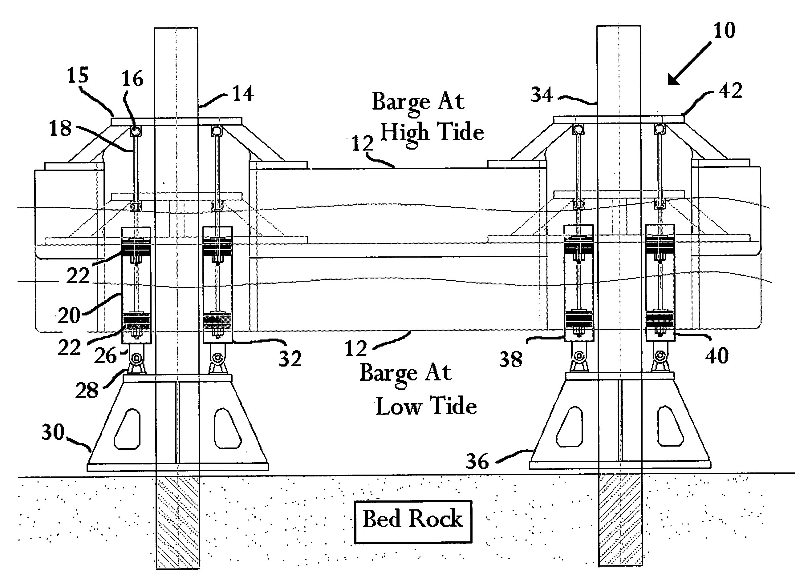
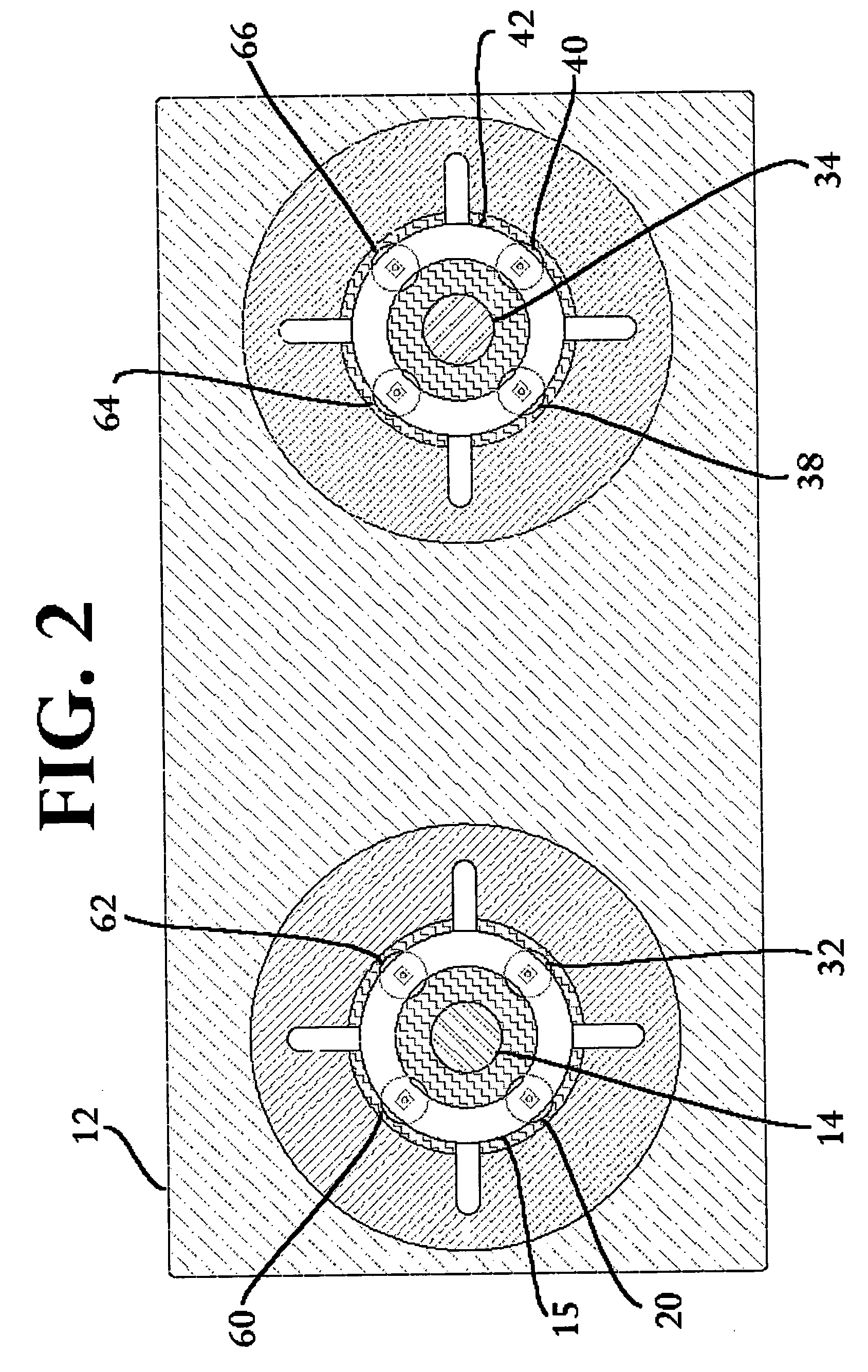
[0010] Yet another preferred embodiment of the present invention uses a single pile or post floating barge or platform that slidably oscillates between vertical limits imposed by wave and tidal action. The single pile is secured to the ocean floor by a support massive enough to resist lateral displacement of ocean flows. The pile or post projects through a platform aperture. Alternatively, the single pile may be embedded in the ocean floor to increase stability against lateral displacement.

Problems solved by technology

Despite this good record the complete blockage of the La Rance estuary has caused significant environmental effects.
The submerged turbine blades have interfered with migration of fish and the overall barrage itself has blocked shipping.
The aforementioned power generating systems, though effective, are big and require a complex series of power grids to convey the power off the barrage or tidal fence to an offshore power collection and distribution system.
Although these systems are smaller and can be located at remote locations, they nevertheless require electricity to be harvested and a grid to be constructed onto these bobbing devices.
The grid in particular is cumbersome and has limited their practical implementation.
This toroidal gas generation system to generate electricity to drive electric DC motors in order to make drinkable water is a desalinization system which works but it is unnecessarily complex.
Where there is a need primarily for fresh water to be generated from a desalinization process especially in remote regions a gas generated gas reactor system is unduly complex and likely to not have the robustness to serve in remote locations.
Furthermore, such a system is very costly.

Method used


Image

  • Barge-mounted tidal-powered desalinization system
  • Barge-mounted tidal-powered desalinization system
  • Barge-mounted tidal-powered desalinization system

Examples


Embodiment Construction

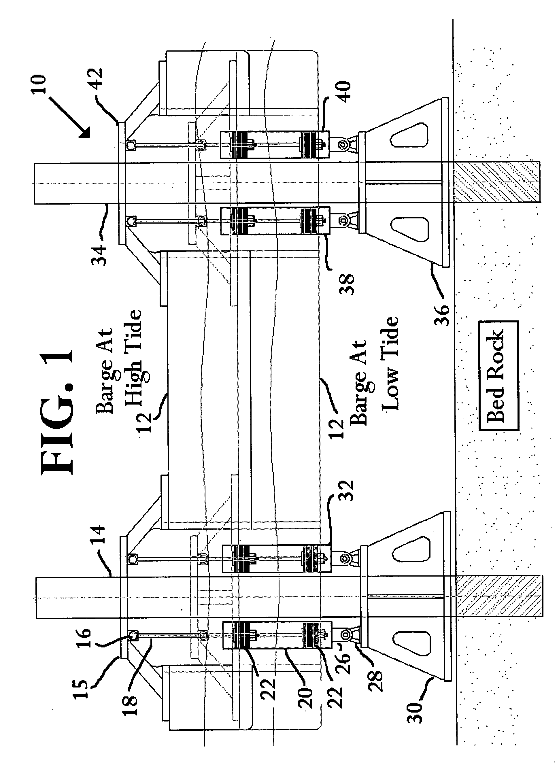
[0019] Arrangement of the barge mounted tidal powered desalinization system comprises a series of pistons mounted to the barge which oscillate within cylinders attached to a shaft which is mounted into the bedrock of the ocean bed. To the shaft are attached a plurality of cylinders where each cylinder has a piston and the piston has a rod which is attached to the barge bottom. As the barge moves up or down with tidal or wave action the pistons move up or down within the cylinders. Through appropriate plumbing valves to direct the flow of saltwater in a one-way direction results in the delivery of saltwater into the reverse osmosis membranes.

[0020] The design of the instant invention using the rising and falling of the tides to create a flow of seawater under pressure suitable for feeding existing reverse osmosis desalinization systems. The design consists of a floating vessel attached to one end of a standard type hydraulic cylinder, the other end of the cylinder is connected to th...


PUM

PropertyMeasurementUnit
pressureaaaaaaaaaa
tidal forcesaaaaaaaaaa
forcesaaaaaaaaaa

Abstract

A tidal-powered desalinization system is mounted on a barge that oscillates about fixed pier structures, generating a two-way pumping action. The two-way pumping action is changed to a single direction flow of seawater. The sea water is directed into an on-board desalinization system. Fresh water is produced and collected in reservoirs, without an intervening generation of electricity.

Description

PRIORITY CLAIM [0001] This application is a continuation of U.S. application Ser. No. 10 / 407,487 filed Apr. 4, 2003, which invention claims priority to U.S. provisional application Ser. No. 60 / 370,085, filed Apr. 4, 2002.FIELD OF THE INVENTION [0002] This invention relates generally to ocean powered desalinization systems. BACKGROUND OF THE INVENTION [0003] It has long been recognized that the oceans provide tremendous potential in kinetic energy which can be harvested to generate electricity. Across the globe there are many tidal electric generation systems installed and in full operation. An example of an installed and fully operational tidal electro-generation system is the barrage system installed near St. Malo on the Brittany Coast in France across the La Rance estuary. The St. Malo system is a 240 megawatt system and has been reliably generating electricity for a good number of years. Despite this good record the complete blockage of the La Rance estuary has caused significant...

Claims


Application Information

Patent Timeline
Patent Type & Authority Applications(United States)
IPC IPC(8): B01D61/10B63B35/44B63J1/00B63J3/04C02F1/44F03B1/00F03B13/26
CPCB01D61/10B63B35/44B63J1/00B63J3/04C02F1/441Y02E10/38F03B13/262F05B2220/62Y02E10/223Y02E10/28F03B3/00Y02A20/131Y02A20/144Y02E10/20Y02E10/30
Inventor STARK, CHRISTIANHOLTON, BRETT
Owner STARK CHRISTIAN
Learn More