Control system for brake-steer assisted parking and method therefor

Inactive Publication Date: 2005-10-27
FORD GLOBAL TECH LLC
View PDF25 Cites 113 Cited by
  • Summary
  • Abstract
  • Description
  • Claims
  • Application Information

AI Technical Summary

Benefits of technology

[0017] The advantage of the invention relative to improving the parkability of the vehicle is particularly suitable for use with long wheelbase vehicles such as full size sport utility vehicles and pickup trucks.
[0018] Oth

Problems solved by technology

One drawback to such a system is that the system adds another steering actuator to the vehicl

Method used


Image

  • Control system for brake-steer assisted parking and method therefor
  • Control system for brake-steer assisted parking and method therefor
  • Control system for brake-steer assisted parking and method therefor

Examples


Embodiment Construction

[0043] In the following figures the same reference numerals will be used to identify the same components. The various terms and values are set forth by way of example and are not meant to be limiting unless specifically set forth in a claim.

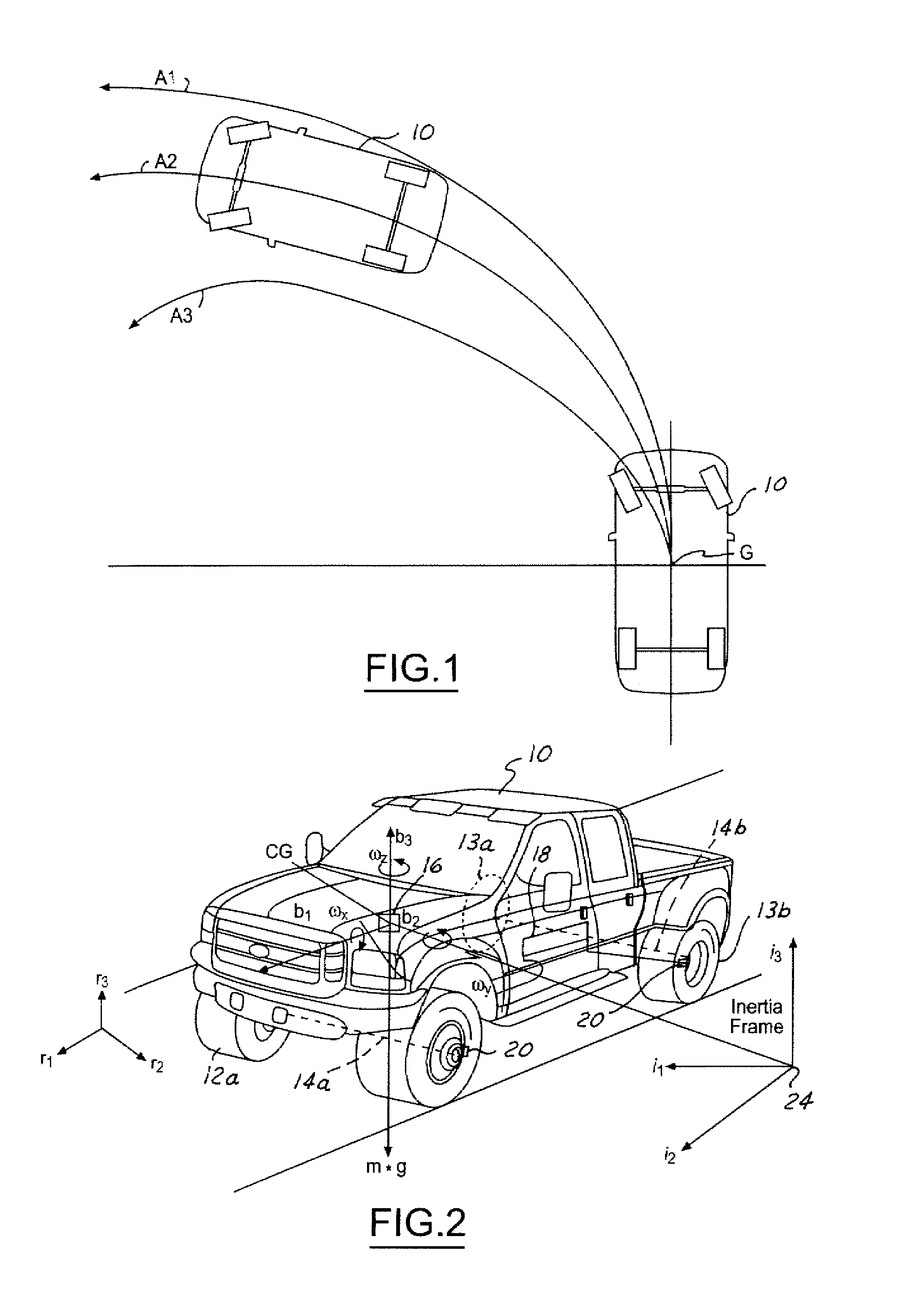
[0044] Referring now to FIG. 1, a vehicle 10 is illustrated traversing three paths. Path A1 is the path a vehicle travels without the invention. Path A2 is a path the vehicle 10 travels with brake-steer. Path A3 is a path the vehicle 10 travels with brake-steer and a controllable suspension component. As is shown, path A2 improves the turning radius over path A1. Path A3 has a reduced or improved turning radius compared to path A2.

[0045] The term brake-steer or brake-steering is used to describe changing a characteristic of the vehicle such as the turning radius or tracking of the vehicle using one or more brakes, the application of differential (positive or negative) torques, or a combination of the braking and differential torques. Positive t...


PUM


Abstract

A system and method of controlling an automotive vehicle includes determining a steering wheel angle, determining a steering wheel direction, determining a steering wheel angular rate and applying brake-steer as a function of steering wheel angle, steering wheel angular rate and steering wheel direction.

Description

CROSS REFERENCE TO RELATED APPLICATIONS [0001] The present invention is related to U.S. application (Attorney Docket No. 81093810 / FGT-1903 PA) entitled “Method and Apparatus of Controlling an Automotive Vehicle Using Brake-Steer as a Function of Steering Wheel Torque”; (Attorney Docket No. 81093816 / FGT-1904 PA) entitled “Method and Apparatus for Controlling an Automotive Vehicle Using Brake-Steer and Normal Load”; (Attorney Docket No. 81093819 / FGT-1905 PA) entitled “Method and Apparatus for Controlling Brake-Steer in an Automotive Vehicle in Reverse”; (Attorney Docket No. 81093821 / FGT-1906 PA) entitled “Method and Apparatus for Controlling Brake-Steer in an Automotive Vehicle in a Forward and Reverse Direction”; (Attorney Docket No. 81093822 / FGT-1907 PA) entitled “Method of Controlling an Automotive Vehicle Having a Trailer”; (Attorney Docket No. 81095826 / FGT-1908 PA) entitled “Method of Controlling an Automotive Vehicle Having a Trailer Using Rear Axle Slip Angle”; (Attorney Docket...

Claims


Application Information

Patent Timeline
IPC IPC(8): B60T8/00B60T8/1755B60T8/24B60W10/18B60W10/20B60W30/06B62D5/04B62D6/00B62D9/00B62D11/08B62D13/06B62D15/02B62D37/00
CPCB60T8/1755B60T8/246B60T2201/10B60T2230/06B60T2260/02B60W10/18B62D15/027B60W30/045B62D6/003B62D9/002B62D11/08B62D13/06B60W10/20B60T8/24
Inventor LU, JIANBOOFFERLE, TIMOTHY G.TSENG, HONGTEI E.RHODE, DOUGLAS S.BROWN, GREGORY P.
Owner FORD GLOBAL TECH LLC
Why Eureka
Try Eureka