Liquid crystal display device and manufacturing method of the same

a technology of liquid crystal display and manufacturing method, which is applied in the field of liquid crystal display device, can solve the problems of reflection luminance, inability to apply plating, and high cost of die-cast components

Inactive Publication Date: 2005-10-27
HITACHI DISPLAYS
View PDF5 Cites 16 Cited by
  • Summary
  • Abstract
  • Description
  • Claims
  • Application Information

AI Technical Summary

Benefits of technology

[0013] The invention is one made in order to solve the above problem of the prior art, and an advantage of the invention is the fact that it is possible to provide a liquid crystal display device ensuring a luminance of the backlight and having the backlight-integrated type resin holder to which the plating has been adhered, and a manufacturing method of the same.
[0014] The above and other advantages and novel characteristics of the invention are made clear by the description in the present specification and the appended drawings.
[0015] Among the inventions disclosed in the present application, if an outline of representative one is simply explaining, it is as follows.
[0016] In order to obtain the advantage mentioned above, the invention is a liquid crystal display device possessing a liquid crystal display panel, a backlight disposed to a back face of the liquid crystal display panel and having at least a light conductor, and a holder accommodating the liquid crystal display panel and the backlight, wherein the holder is constituted by a holder in which a 1st resin to which a plating can be applied and a 2nd white resin whose condition under which the plating adheres is different from the 1st resin have been molded in 2 colors, the plating is applied to the 1st resin, and the 2nd white resin to which no plating is applied is disposed to a side face of the light conductor.
[0017] Further, the invention is a method of manufacturing a liquid crystal display device possessing a liquid crystal display panel, a backlight disposed to a back face of the liquid crystal display panel and having at least a light conductor, and a holder accommodating the liquid crystal display panel and the backlight, comprising a holder molding process which molds in 2 colors a 1st resin to which a plating can be applied and a 2nd white resin whose condition under which the plating adheres is different from the 1st resin, and a plating process which, after the holder molding process, applies the plating only to the 1st resin between the 1st resin and the 2nd resin, and in that the 2nd white resin to which no plating is applied is disposed to a side face of the light conductor.
[0018] Here, it is desirable that the 1st resin is a plastic alloy containing polycarbonate, and the 2nd resin is polycarbonate.

Problems solved by technology

As mentioned above, for the frame (LCA), the Mg die-cast component is used, but there is a problem that the Mg die-cast component is expensive and inferior in its mass productivity.
However, in the backlight-integrated type resin holder, there has been a problem that it is impossible to apply a plating in order to ensure a reflection luminance at the mold disposed to a side face of the light conductor 10.

Method used


Image

  • Liquid crystal display device and manufacturing method of the same
  • Liquid crystal display device and manufacturing method of the same
  • Liquid crystal display device and manufacturing method of the same

Examples


Embodiment Construction

[0027] Hereunder, an embodiment of the invention is explained by referring to the drawings.

[0028] Incidentally, in all drawings for explaining the embodiment, the same reference numeral is applied to one having the same function, and its repeated explanation is omitted.

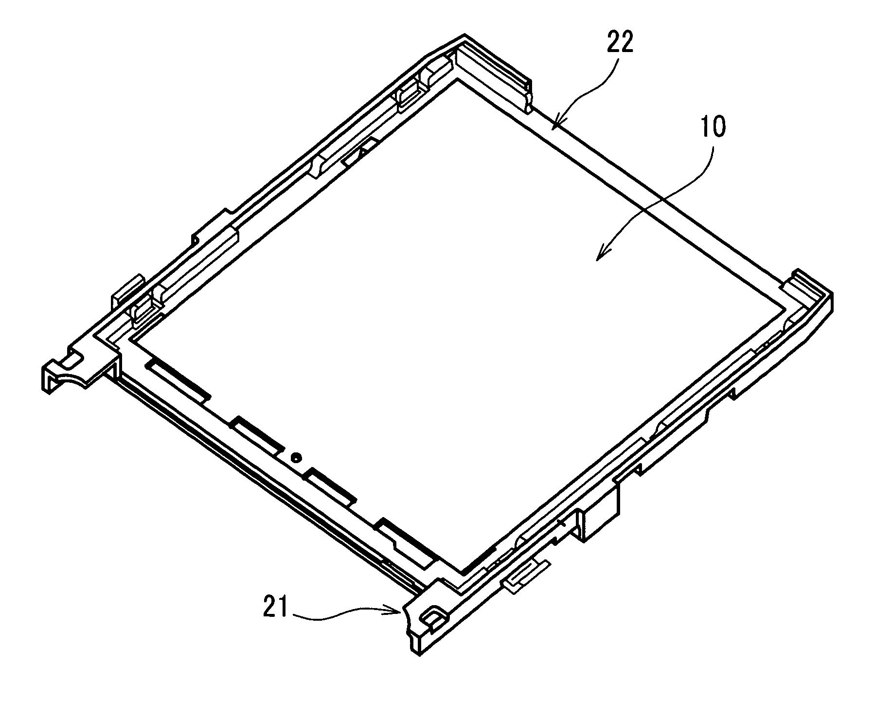
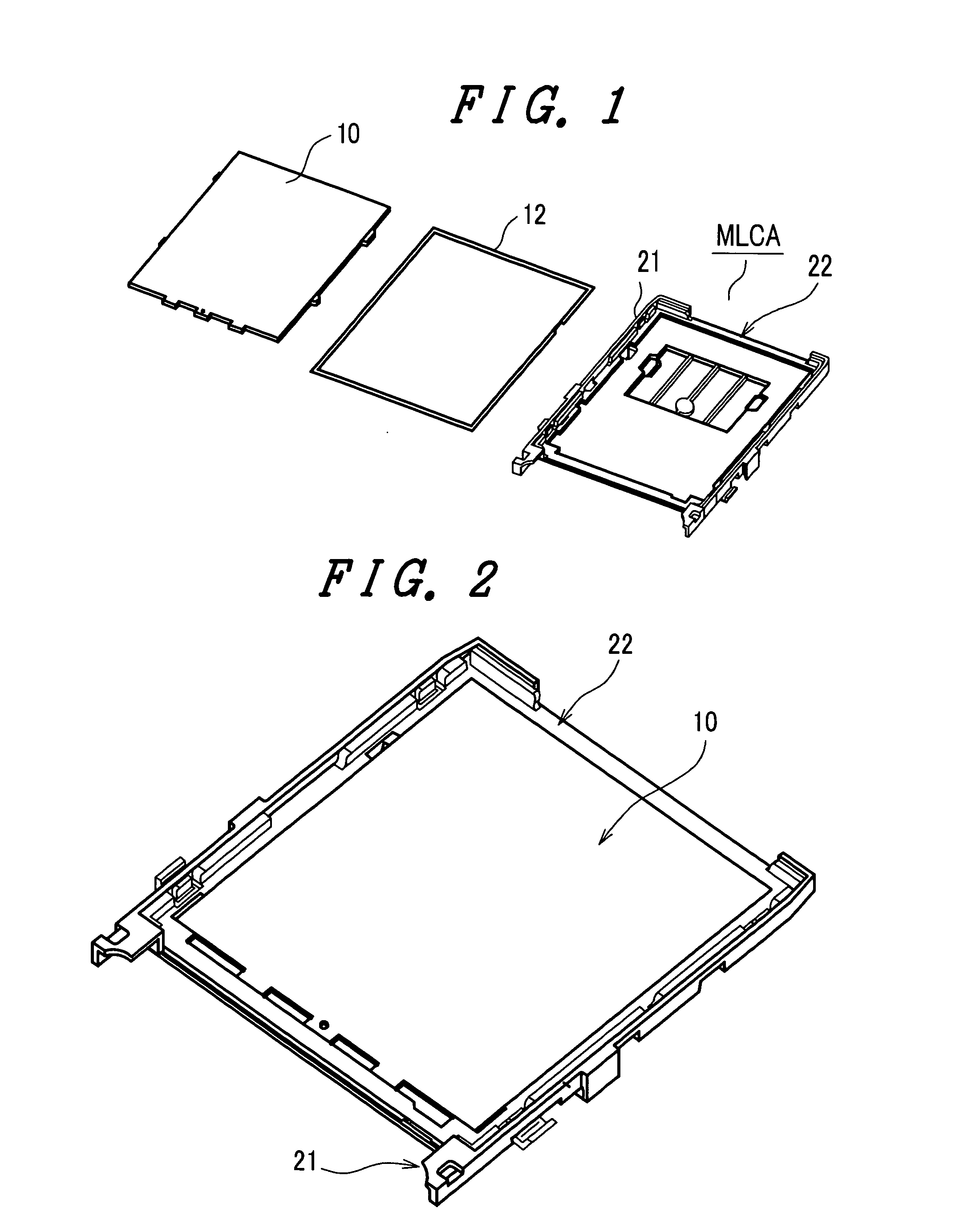
[0029]FIG. 1 is an exploded, developed view showing a constitution of a backlight side of a liquid crystal display module of an embodiment of the invention, and FIG. 2 is a perspective view showing a state that each component shown in FIG. 1 has been assembled.

[0030] In FIG. 1 and FIG. 2, 10 denotes the light conductor, 12 the reflecting sheet, and an MLCA a backlight-integrated type resin holder.

[0031] The light conductor 10 and the reflecting sheet 12 are disposed in the backlight-integrated type resin holder (MLCA) in order shown in FIG. 1, and become a state shown in FIG. 2. Under the state shown in FIG. 2, on its upper part there is disposed the liquid crystal display panel (LCD), and thereby the liquid cryst...


PUM

PropertyMeasurementUnit
colorsaaaaaaaaaa
electrical conductivityaaaaaaaaaa
strengthaaaaaaaaaa

Abstract

There is provided a liquid crystal display device ensuring a luminance of a backlight and having a backlight-integrated type resin holder to which a plating has been adhered. A liquid crystal display device including a liquid crystal display panel, a backlight disposed to a back face of the liquid crystal display panel and having at least a light conductor, and a holder accommodating the liquid crystal display panel and the backlight, wherein the holder is a holder in which a 1st resin to which a plating can be applied and a 2nd white resin whose condition under which the plating adheres is different from the 1st resin have been molded in 2 colors, the plating is applied to the 1st resin, and the 2nd white resin to which no plating is applied is disposed to a side face of the light conductor. It is desirable that the 1st resin is a plastic alloy containing polycarbonate, and the 2nd resin is polycarbonate.

Description

[0001] The present application claims priority from Japanese application JP2004-126183 filed on Apr. 22, 2004, the content of which is hereby incorporated by reference into this application. BACKGROUND OF THE INVENTION [0002] The present invention concerns a liquid crystal display device and a manufacturing method of the same, and especially relates to a technique effective for being applied to a holder retaining a liquid crystal display panel. [0003] In recent years, the small liquid crystal display panel (for example, liquid crystal display panel of a TFT (Thin Film Transistor) system, and the like) is widely used as a display part of a portable equipment such as portable telephone as shown, for example, in FIG. 4A and FIG. 4B. [0004] Incidentally, FIG. 4A and FIG. 4B are drawings for explaining the portable telephone in which the liquid crystal display panel of the TFT system is used as the display part, wherein FIG. 4A is a front view, and FIG. 4B a side view. [0005] In FIG. 4A ...

Claims


Application Information

Patent Timeline
Patent Type & Authority Applications(United States)
IPC IPC(8): G02F1/1333G02F1/13G02F1/13357
CPCG02F1/1336G02F1/133308E06B9/54E06B9/78E06B2009/527E06B2009/543
Inventor NAKANISHI, NORIOMITANI, HIDEO
Owner HITACHI DISPLAYS
Why Eureka
Try Eureka