Super tweeter

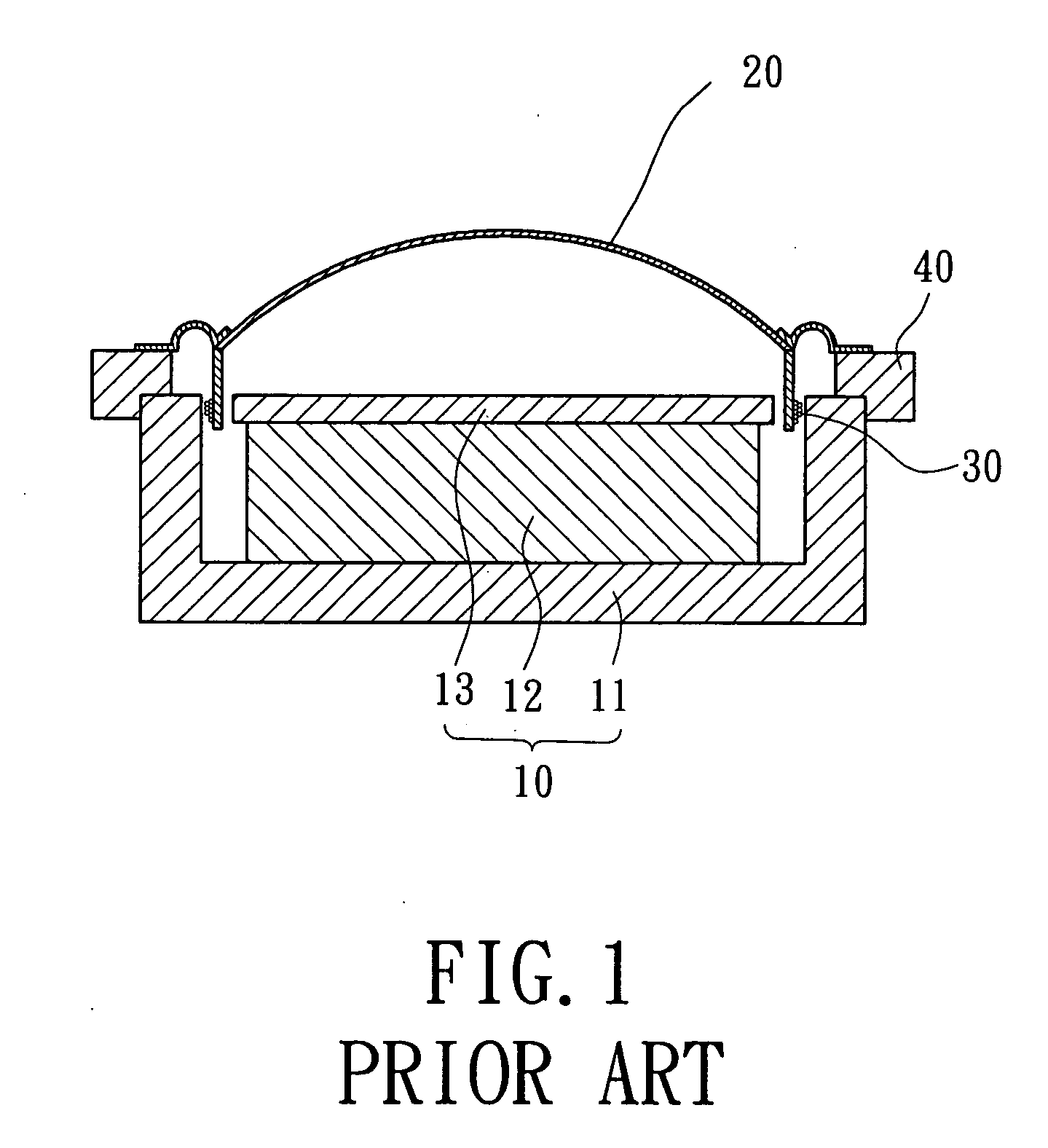
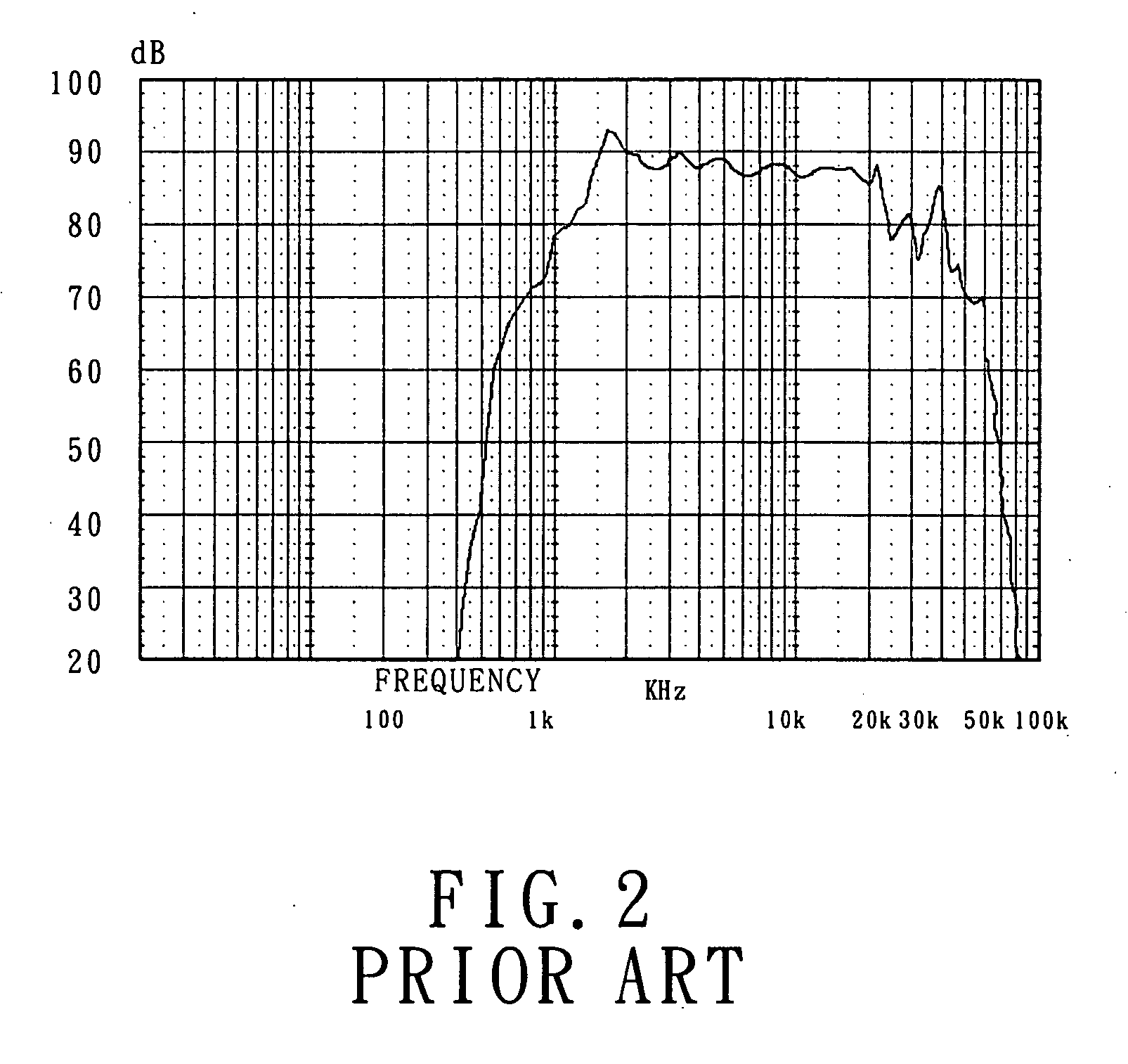
a tweeter and super technology, applied in the direction of transducer details, electrical transducers, electrical apparatus, etc., can solve the problems of random reflective waves that interfere with one another, the diaphragm b>20/b> cannot effectively balance vibrations, and the diaphragm cannot effectively absorb lagging vibration waves, etc., to achieve excellent sound quality

Active Publication Date: 2005-10-27
SUN TECHN ELECTRIC
View PDF2 Cites 15 Cited by
  • Summary
  • Abstract
  • Description
  • Claims
  • Application Information

AI Technical Summary

Benefits of technology

[0006] An object of the present invention is to provide a super tweeter that c...

Problems solved by technology

Nevertheless, it was found that the diaphragm 20 could not effectively balance the vibrations or could not effectively absorb the l...

Method used


Image

  • Super tweeter
  • Super tweeter
  • Super tweeter

Examples


Embodiment Construction

[0019] Preferred embodiments of the present invention are now to be described hereinafter in detail, in which the same referential numerals are used for the same parts as those in the prior art to avoid redundant description.

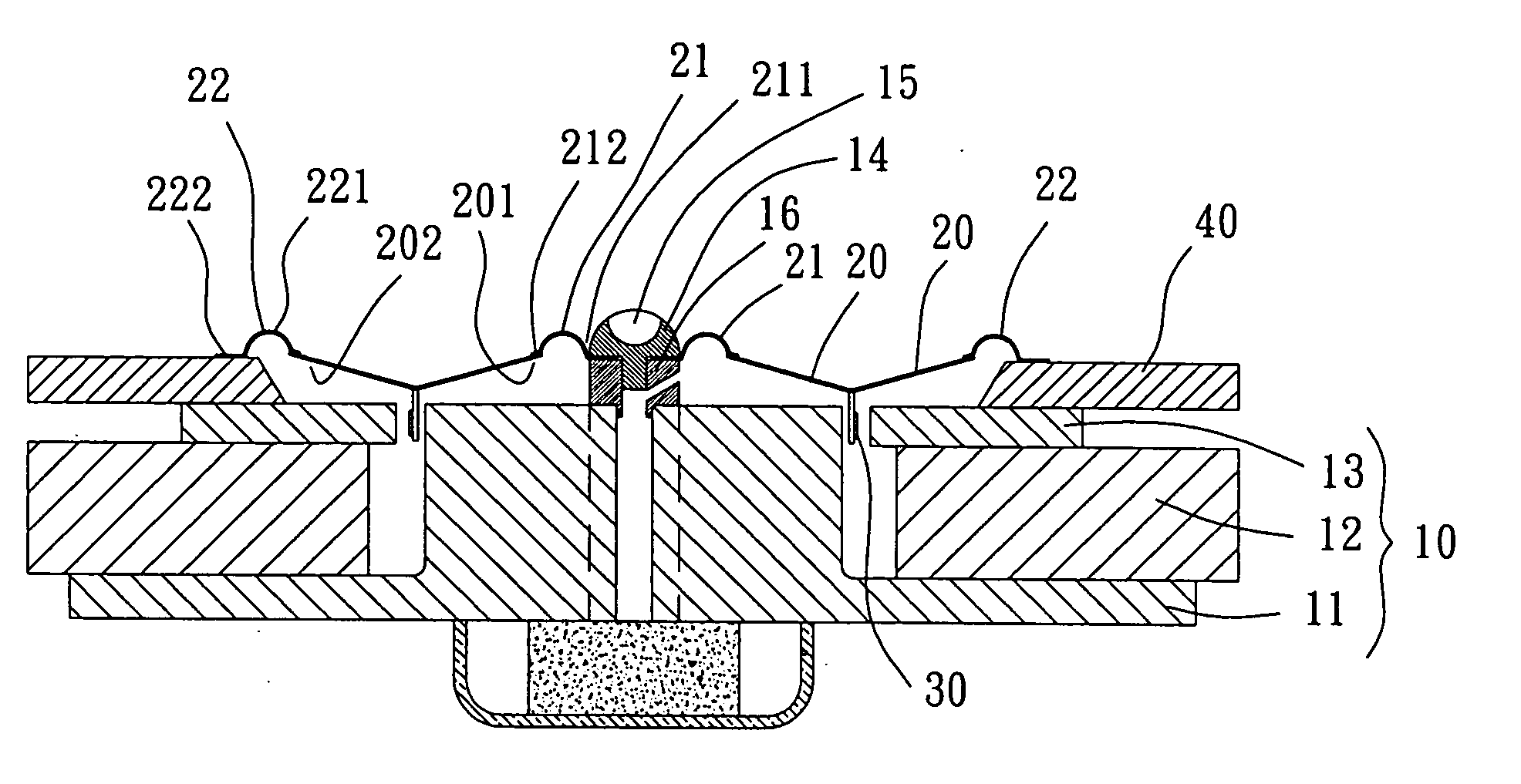
[0020] Referring to FIG. 3, a super tweeter in accordance with the present invention includes a magnetic base 10, a diaphragm 20, an annular inner supporting member 21, an annular outer supporting member 22, a voice coil 30, and a frame 40. The magnetic base 10 includes a T-iron 11, a magnet 12, and a pole plate 13. The diaphragm 20 is connected to the annular inner supporting member 21, the annular outer supporting member 22, and the voice coil 30. Provision of the annular inner and outer supporting members 21 and 22 and the voice coil 30 allows the diaphragm 20 to generate sound waves in the frequency range between 500 Hz and 100 kHz, which will be described in detail later.

[0021] Still referring to FIG. 3, the T-iron 11 of the magnetic base 10 is made of a ...


PUM


Abstract

A super tweeter includes a magnetic base, a voice coil, a frame annularly mounted to the magnetic base, a central supporting member mounted on a central portion of the magnetic base, a diaphragm, an annular inner supporting member, and an annular outer supporting member. The diaphragm is connected between an annular outer side of the annular inner supporting member and an annular inner side of the annular outer supporting member. An annular inner side of the annular inner supporting member is engaged with the central supporting member. An annular outer side of the annular outer supporting member is engaged with the frame. The annular inner supporting member and the annular outer supporting member cause the diaphragm to vibrate in a balanced manner, generating super high frequency range of sound waves.

Description

BACKGROUND OF THE INVENTION [0001] 1. Field of the Invention [0002] The present invention relates to a super tweeter that can produce excellent sound quality in the frequency range between 500 Hz and 100 kHz. [0003] 2. Description of Related Art [0004]FIG. 1 of the drawings illustrates a typical conventional tweeter. The tweeter includes a magnetic base 10, a diaphragm 20, a voice coil 30, and a frame 40. The magnetic base 10 includes a U-iron 11, a magnet 12, and a pole plate 13. The voice coil 30 is bonded by adhesive to the diaphragm 20. The voice coil 30 is formed by means of winding a copper wire and positioned in an annular gap between the U-iron 11 and the pole plate 13. The frame 40 is annularly mounted to the magnetic base 10, with the diaphragm 20 being bonded to the frame 40. [0005] The tweeter having the above-mentioned simple structure can be easily manufactured at a low cost. Nevertheless, it was found that the diaphragm 20 could not effectively balance the vibrations ...

Claims


Application Information

Patent Timeline
IPC IPC(8): H04R1/02H04R1/20H04R7/12H04R9/06
CPCH04R9/06H04R7/12
Inventor CHANG, TZU-CHUNG
Owner SUN TECHN ELECTRIC
Why Eureka
Try Eureka