Discharge check valve assembly for use with hermetic scroll compressor

Inactive Publication Date: 2005-10-27
DANFOSS MANEUROP
View PDF8 Cites 17 Cited by
  • Summary
  • Abstract
  • Description
  • Claims
  • Application Information

AI Technical Summary

Benefits of technology

[0009] It is an object of the invention to provide a leak tight discharge check valve assembly for a hermetic scroll compressor, which is easy and inexpensive to manufacture and to install.
[0011] It is another object of the invention to provide a discharge check valve assembly having a discharge valve subassembly which may be removed from the compressor without requiring removal of the permanently attached discharge fitting.
[0021] In an even further aspect, the guiding portion of the valve member extends through the bore of the valve body and a retaining element is coupled to the guiding portion of the valve member to prevent the guiding portion from sliding out of the bore.

Problems solved by technology

Moreover, once these known discharge check valves are assembled to the compressor shell, they cannot be removed without also detaching the discharge fitting from the compressor shell.
Further, these disk type valves are not completely tight, due to insufficient closure force on the unbiased valve element and manufacturing tolerances for the valve element and the valve seat.

Method used


Image

  • Discharge check valve assembly for use with hermetic scroll compressor
  • Discharge check valve assembly for use with hermetic scroll compressor
  • Discharge check valve assembly for use with hermetic scroll compressor

Examples


Embodiment Construction

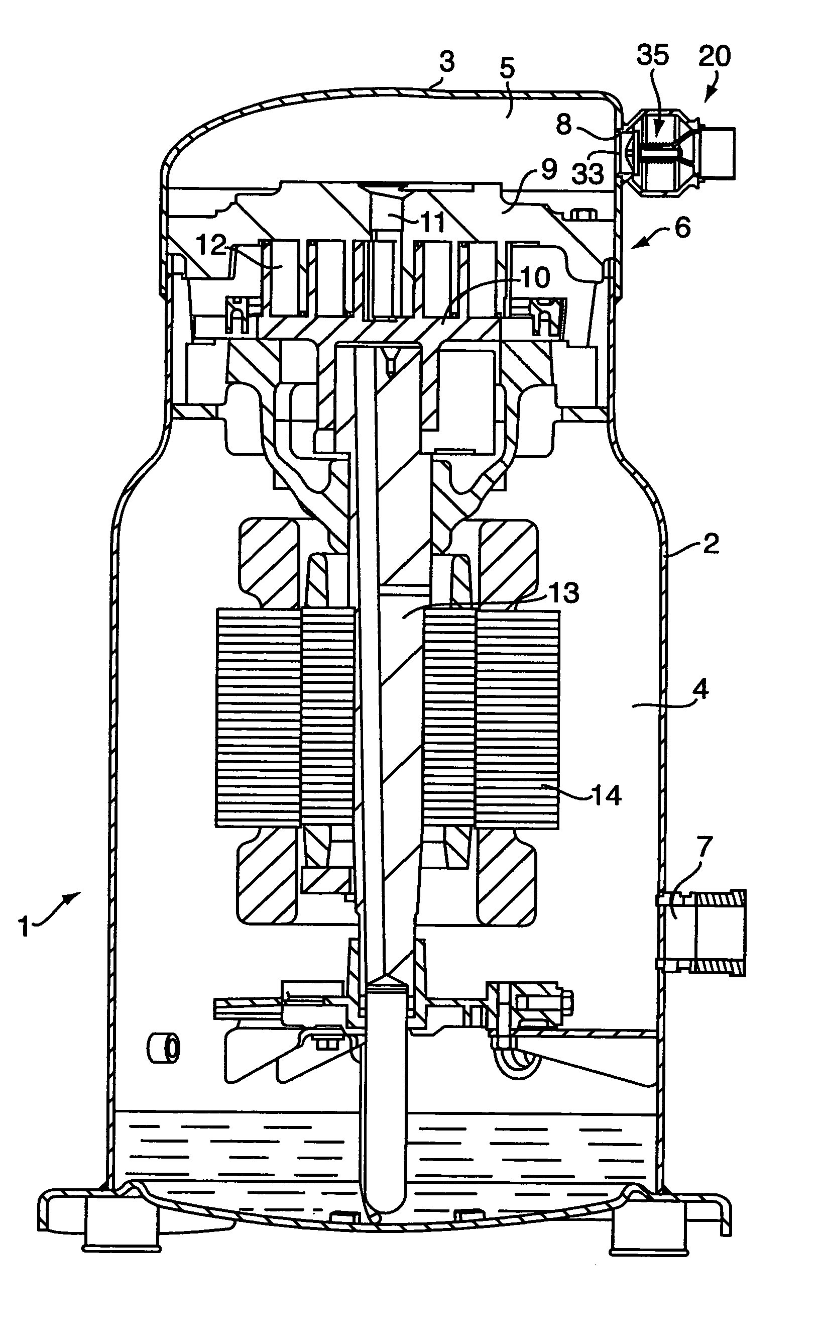
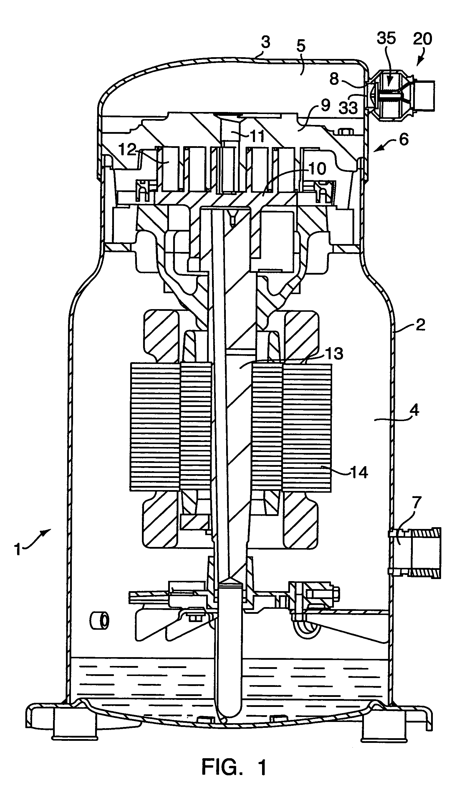
[0038]FIG. 1 shows a hermetic scroll compressor 1 including an enclosure or shell 2, an upper part of which is formed by a cap 3. The volume inside the enclosure 2 is separated into two compartments, a low-pressure fluid-inlet compartment 4, and a high-pressure compartment 5 for outlet of compressed fluid. These two compartments, 4 and 5, are separated by a fluid compression stage 6. Fluid is admitted into the low-pressure compartment via an inlet orifice 7 and compressed fluid is discharged from the high-pressure compartment 5 via an orifice 8 in cap 3. A discharge check valve assembly 20 is arranged in orifice 8.

[0039] The compression stage 6 includes a fixed spiral element 9 and a movable spiral element 10, these two spiral elements having interpenetrating parts and defining compression pockets 12. A shaft 13 drives the movable spiral element 10 in an orbital movement. Movement of shaft 13 is provided by a motor 14. During the orbital movement of the spiral element 10, the compr...


PUM


Abstract

A discharge check valve assembly for use with a hermetic scroll compressor having a compressor shell is provided. The discharge check valve assembly includes a valve housing and a valve seat located within the valve housing. The valve housing is configured to mount the discharge check valve assembly to the compressor shell. The discharge check valve assembly also includes a discharge fitting and a valve subassembly. The discharge fitting is configured to mount to the compressor shell and configured to connect to a connecting tube in fluid communication with a high-pressure system. The valve subassembly has a valve member movable between an open position and a closed position. Additionally, the valve subassembly is configured to be inserted through the discharge fitting into the valve housing.

Description

CROSS REFERENCE TO RELATED APPLICATIONS [0001] This application is entitled to the benefit of and incorporates by reference essential subject matter disclosed in Provisional Patent Application Ser. No. 60 / 565,463 filed on Apr. 26, 2004.FIELD OF THE INVENTION [0002] The invention relates to a discharge check valve assembly for use with a hermetic scroll compressor. BACKGROUND OF THE INVENTION [0003] Scroll compressor machines, which have two intermeshed involutes or scrolls, provide an efficient way to compress fluids, including gases or mixtures thereof. In operation, one of the scrolls is fixed and the other, an orbiting scroll, is driven by a motor so that it orbits in relation to the fixed scroll. Fluid enters the compressor shell through a low-pressure fluid inlet port and exits through a high-pressure discharge port. The low pressure fluid enters the outer pockets defined by the intermeshed scrolls and is moved toward the center of the intermeshed scrolls or spirals, thereby de...

Claims


Application Information

Patent Timeline
IPC IPC(8): F04B17/00F04B39/00F04B39/02F04B53/10
CPCF04B39/023F04B53/1087F04C2240/806F04C23/008F04C29/126F04C18/0215Y10S417/902Y10T137/7559Y10T137/7932
Inventor GINIES, PIERRESOULAS, PIERRENICOLAISEN, HOLGER
Owner DANFOSS MANEUROP
Why Eureka
Try Eureka