Laminated spacer fabric

a spacer fabric and foam technology, applied in the field of foam spacer fabric, can solve the problems of puckering and air pockets, affecting the comfort of seating or objects utilizing the foam fabric, and forming pockets or gaps between the foam padding and outer layers,

Active Publication Date: 2005-10-27
HIGHLAND IND
View PDF27 Cites 16 Cited by
  • Summary
  • Abstract
  • Description
  • Claims
  • Application Information

AI Technical Summary

Problems solved by technology

Additionally, in certain situations, pockets or gaps may be formed between the padding and outer layers.
These problems create an undesirable appearance and may decrease the value of a seat or the object utilizing the sewn fabric.
The puckering and air pockets may also create an uncomfortable surface when contacted by a person sitting or leaning against the sewn fabric.
The conventional covered spacer fabrics generally result in increased costs for the manufacturer.
After shipment, the spacer fabric tends to lose its dimensions.
As a result, the process of sewing a precut outer layer to the spacer fabric is difficult and time-consuming.
Another drawback of the conventional spacer fabric is that the edges of the conventional fabric fray and lack dimensional stability.
However, typical seats in spacer fabrics wear quickly and may chill or overheat an occupant due to improper air flow.
Moreover, there are inherent difficulties in mating a rigid or semi-rigid surface material (e.g. leather) with a non-rigid spacer material through a sewing process.
One problem is that the dimensions of the cut pieces of spacer material tend to change size after cutti

Method used


Image

  • Laminated spacer fabric
  • Laminated spacer fabric
  • Laminated spacer fabric

Examples


Embodiment Construction

[0021] Hereinafter, embodiments of the present invention will be described with reference to the attached drawings.

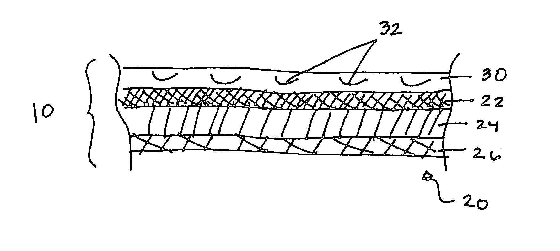
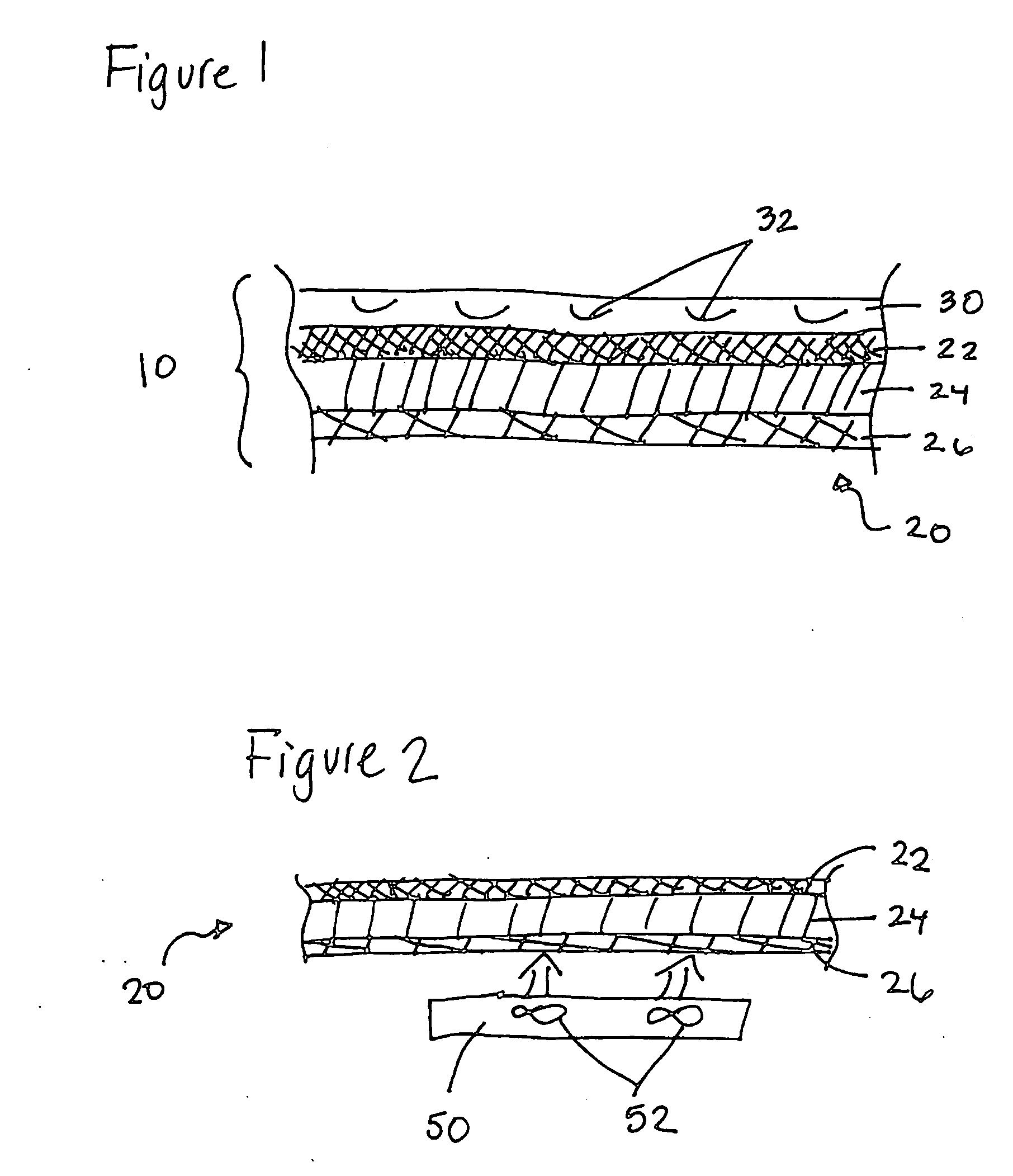
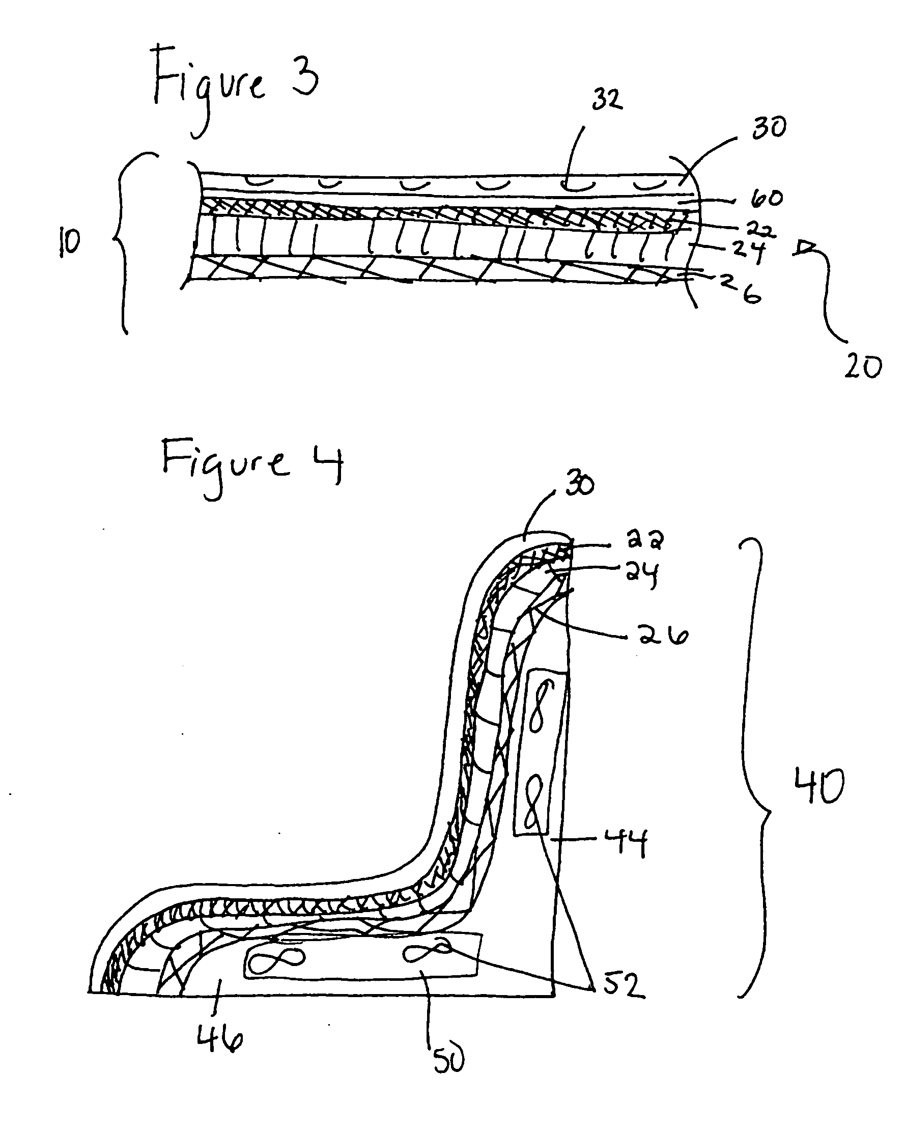
[0022] According to an embodiment of the present invention, a laminated material 10 is provided. As shown in FIG. 5, the laminated material 10, may include a cover layer 30 and a porous material layer 15. The cover layer 30 may be porous and may include a poly-vinyl chloride polymer coated material, leather, body cloth fabric, a thermoplastic olefin coated material, a polyurethane coated material, or any other suitable material. The porous material layer 15 may be a reticulated foam, a nonwoven textile, or preferably a spacer fabric.

[0023] According to an alternative embodiment of the present invention, the porous material layer 15 may comprise a spacer fabric 20. The spacer fabric 20, as shown in FIGS. 1 and 2, may include a first fabric layer 22, a second fabric layer 26 and a pile layer 24 which connects the first 22 and second 26 fabric layers. The fabric layers 2...


PUM

PropertyMeasurementUnit
Linear densityaaaaaaaaaa
Percent by massaaaaaaaaaa

Abstract

A laminated material including a decorative or functional cover layer laminated to a porous material layer. The cover layer may include a rigid, semi-rigid or flexible material and the porous spacer material layer may include a reticulated foam, nonwoven textile, or a spacer fabric. The cover layer is laminated onto the porous material layer, increasing the seam strength, durability and dimensional stability of the material.

Description

BACKGROUND OF THE INVENTION [0001] The present invention relates to a laminated spacer fabric. [0002] Certain conventional fabrics include a padding or porous layer covered by an outer layer. The underlying padding or porous layer is typically sewn to the outer layer. The outer layer in the conventional sewn assembly may pucker or have other surface deformations resulting from the sewn seams. Additionally, in certain situations, pockets or gaps may be formed between the padding and outer layers. These problems create an undesirable appearance and may decrease the value of a seat or the object utilizing the sewn fabric. The puckering and air pockets may also create an uncomfortable surface when contacted by a person sitting or leaning against the sewn fabric. [0003] The porous or padding layer may be a spacer fabric. The conventional covered spacer fabrics generally result in increased costs for the manufacturer. Rolls or cut pieces of the spacer fabric are produced, pre-cut, and shi...

Claims


Application Information

Patent Timeline
IPC IPC(8): B32B5/02B32B5/22B32B5/26B32B5/32B60N2/70
CPCB32B5/02B60N2/70D04B21/10D10B2403/0112Y10T428/24942D10B2505/08Y10T428/24174Y10T428/24033D10B2403/0213D04B21/16Y10T442/10Y10T442/488Y10T428/23914B32B5/26B32B5/06B32B7/12B32B2307/724
Inventor SCHINDZIELORZ, MICHAELPRUITT, JIMMYWAGNER, CARL
Owner HIGHLAND IND
Why Eureka
Try Eureka