End member for a bone fusion implant

a bone fusion and end member technology, applied in the field of end members of bone fusion implants, can solve the problems of restoring the natural and affecting the normal anatomical length and shape of any long bone with a bone defect. , to achieve the effect of promoting bone fusion and restoring spinal anatomy and stability, the problem of the most difficult aspects of treatmen

Inactive Publication Date: 2005-10-27
DEPUY SYNTHES PROD INC
View PDF11 Cites 14 Cited by
  • Summary
  • Abstract
  • Description
  • Claims
  • Application Information

AI Technical Summary

Benefits of technology

[0010] In order to secure the end member to the implant, the second portion may have a hole for receiving a fastener. Alternatively, the exterior surface of the second portion may have protuberances that are sized to fit within the apertures of the implant. In an exemplary embodiment, the second portion comprises a plurality of tabs to secure the end member to the implant. These tabs may be resilient so that the tabs flex inward upon insertion of the second portion into the implant and flex back outward to create a friction fit that secures the end member to the implant. In another embodiment, the end member includes a projection hinged or pivotably connected to the first portion, a threaded bore in the second portion, and a set screw insertable into the threaded bore. Threading the set screw into the bore causes outward movement of the projection to thereby secure the end member to the implant.

Problems solved by technology

The treatment and management of bone defects remains one of the most challenging aspects of orthopaedics.
Restoring natural anatomical length and shape of any long bone with a bone defect is problematic.
Restoring spinal anatomy and stability and promoting bone fusion are even more difficult in a corpectomy, a surgical procedure in which a section of one or several vertebrae is removed.
Although the clinical results of mesh and allograft implants have generally been positive, one possible clinical complication is subsidence of the implant.
Excessive sinking of the ends of the implant into the bone with which they contact is especially troublesome whenever the bone is extremely porous.
However, the end rings disclosed have no provisions for holding, insertion, and distraction instruments.
Thus, implantation can be difficult.
Furthermore, there can be excessive movement between the bone and the disclosed end rings after implantation.
This may delay, and perhaps prevent bone fusion.

Method used


Image

  • End member for a bone fusion implant
  • End member for a bone fusion implant
  • End member for a bone fusion implant

Examples


first embodiment

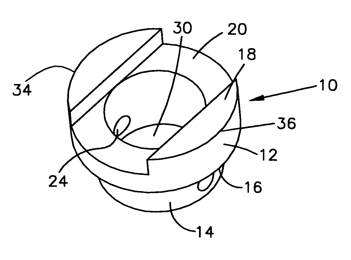
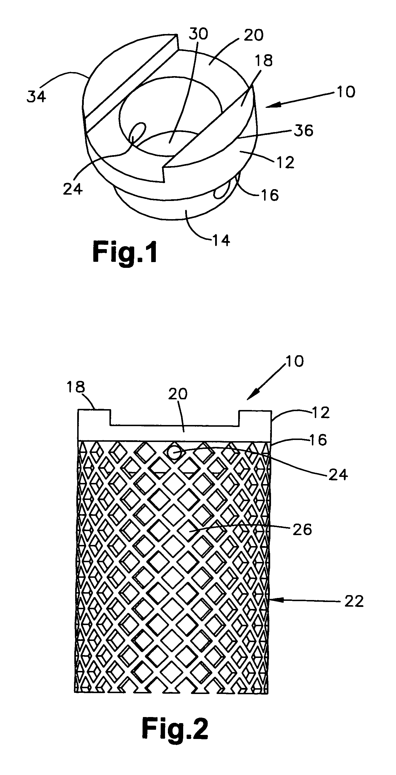
[0030]FIG. 1 shows an end member 10 according to the present invention. End member 10 has a first portion. 12 and a second portion 14. As first portion 12 is larger than second portion 14, a shoulder 16 is formed at the intersection between first and second portions 12, 14. A top surface 18 of first portion 12 is provided with a first slot 20 for accommodating surgical instrumentation such as holding, insertion, and / or distraction instruments. Top surface 18 is shown in FIG. 1 with a round shape. However, as will be evident from the other embodiments, top surface 18 can have any suitable shape. Preferably, top surface 18 has a shape that matches the shape of the bone it will contact.

[0031] Second portion 14 is also shown having a round shape. As was the case for top surface 18, second portion 14 can have any suitable shape. Preferably, the shape of second portion 14 matches the shape of the bone fusion implant used with the end member. As best seen in FIG. 2, second portion 14 is si...

second embodiment

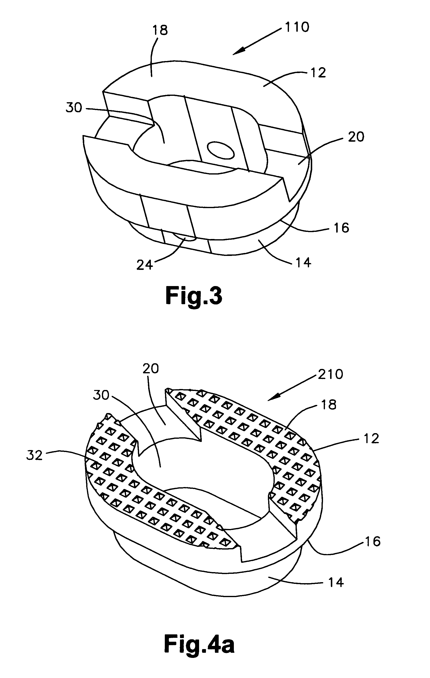
[0033]FIG. 3 shows an end member 110 according to the present invention. In general, most of the structure of end member 110 (as well as the embodiments described below) is like or comparable to the structure of end member 10 and, accordingly the same reference numeral is used for like components and discussion of those like components is not believed necessary. End member 110 has an oval or oblong shape and would be used in situations in which the surrounding bone (and consequently the bone fusion implant) is substantially oval or oblong. When the end member has a non-symmetrical shape like end member 110, first slot 20 can be provided in any orientation. For example, first slot 20 is shown running along the long axis of end member 110, but could run in any direction to be oriented differently with respect to the surrounding bone. The variability in the placement of first slot 20 means that first slot 20 can be positioned as best suited for the particular surgical approach that is ...


PUM


Abstract

An end member for use with a bone fusion implant is disclosed. The end member has a first portion, a second portion, and a shoulder connecting the two portions. The second portion is sized to fit within the interior of the bone fusion implant in such a fashion that the shoulder rests on the edge of the implant. The top surface of the first portion has at least one slot to receive a surgical instrument such as an inserter and / or distractor to facilitate implantation of the end member and bone fusion implant. The top surface may also have teeth to provide initial mechanical stability between the bone and end plate and promote bone fusion.

Description

CROSS-REFERENCE TO RELATED APPLICATIONS [0001] This application is a continuation application of U.S. patent application Ser. No. 09 / 497,123 filed Feb. 3, 2000, from which priority of Provisional Application no. 60 / 118,806 filed on Feb. 4, 1999 is claimed under 35 U.S.C. § 119(e), both of which are incorporated by reference herein in their entirety.FIELD OF THE INVENTION [0002] The present invention relates to a device for bone fusion, and in particular to an end member for a bone fusion implant. BACKGROUND OF THE INVENTION [0003] The treatment and management of bone defects remains one of the most challenging aspects of orthopaedics. Bone defects occur in a wide variety of clinical situations. Restoring natural anatomical length and shape of any long bone with a bone defect is problematic. Additionally, whenever a vertebra has to be removed, it is necessary to insert a vertebral spacer to restore the natural length and curvature of the spine as well as to promote bone fusion. Resto...

Claims


Application Information

Patent Timeline
Patent Type & Authority Applications(United States)
IPC IPC(8): A61F2/00A61F2/28A61F2/30A61F2/44A61F2/46
CPCA61F2/28A61F2310/00359A61F2/44A61F2/4465A61F2/4611A61F2002/2835A61F2002/30115A61F2002/30126A61F2002/302A61F2002/30228A61F2002/3023A61F2002/30233A61F2002/30235A61F2002/30324A61F2002/30354A61F2002/30355A61F2002/30426A61F2002/30484A61F2002/30492A61F2002/305A61F2002/30507A61F2002/30626A61F2002/30747A61F2002/30785A61F2002/30787A61F2002/3082A61F2002/30843A61F2002/30892A61F2002/30912A61F2002/4475A61F2220/0025A61F2220/0033A61F2230/0006A61F2230/0008A61F2230/0065A61F2230/0069A61F2250/0036A61F2310/00011A61F2/30744A61F2002/30593A61F2002/30624
Inventor MESSERLI, DOMINIQUE D.PAUL, DAVID C.
Owner DEPUY SYNTHES PROD INC
Why Eureka
Try Eureka