Wheel and method of manufacturing the same

a technology of rim flanges and wheels, which is applied in the field of wheels, can solve the problems of corrosion achieve the effects of reducing the strength and rigidity deterioration in the design characteristics of wheels, and increasing the strength of rim flange parts

a technology of rim flanges and wheels, which is applied in the field of wheels, can solve the problems of corrosion achieve the effects of reducing the strength and rigidity deterioration in the design characteristics of wheels, and increasing the strength of rim flange parts

US20050241740A1Active Publication Date: 2005-11-03WORK

Image

  • Wheel and method of manufacturing the same
  • Wheel and method of manufacturing the same
  • Wheel and method of manufacturing the same

Examples


Embodiment Construction

[0028] An embodiment of the present invention will be described below with reference to the attached figures.

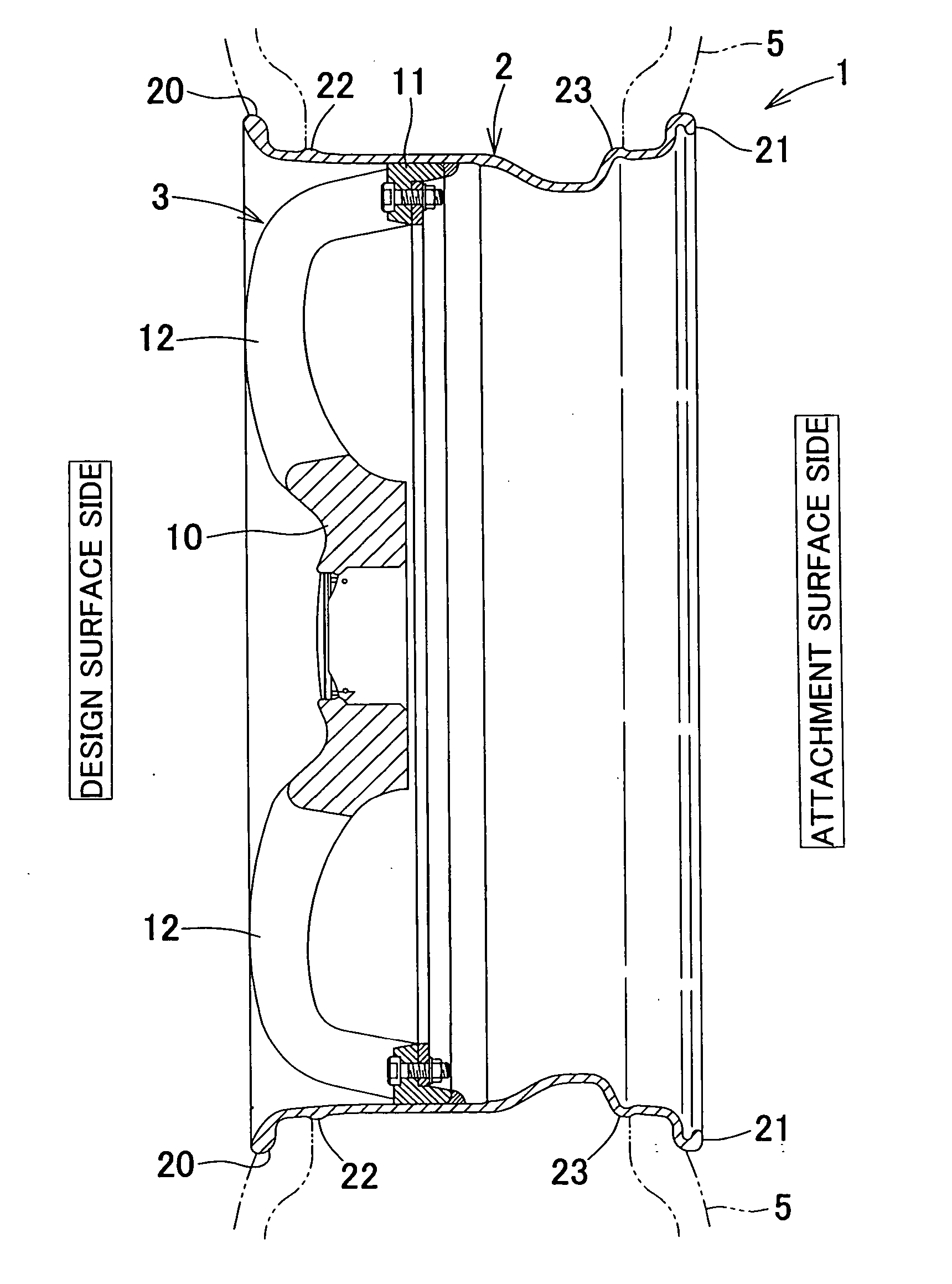
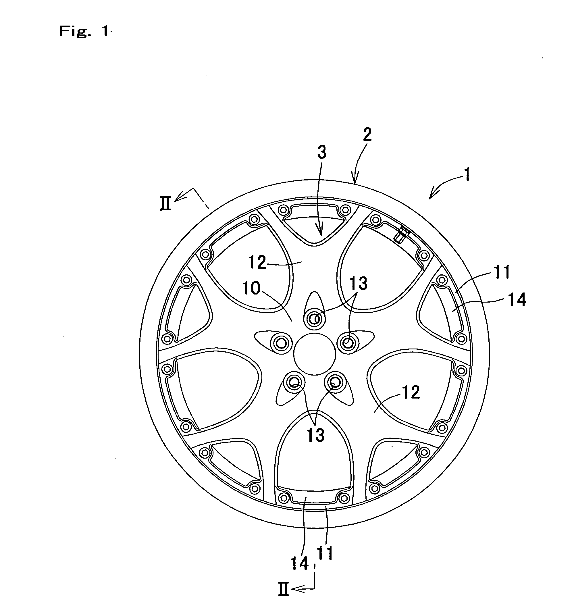
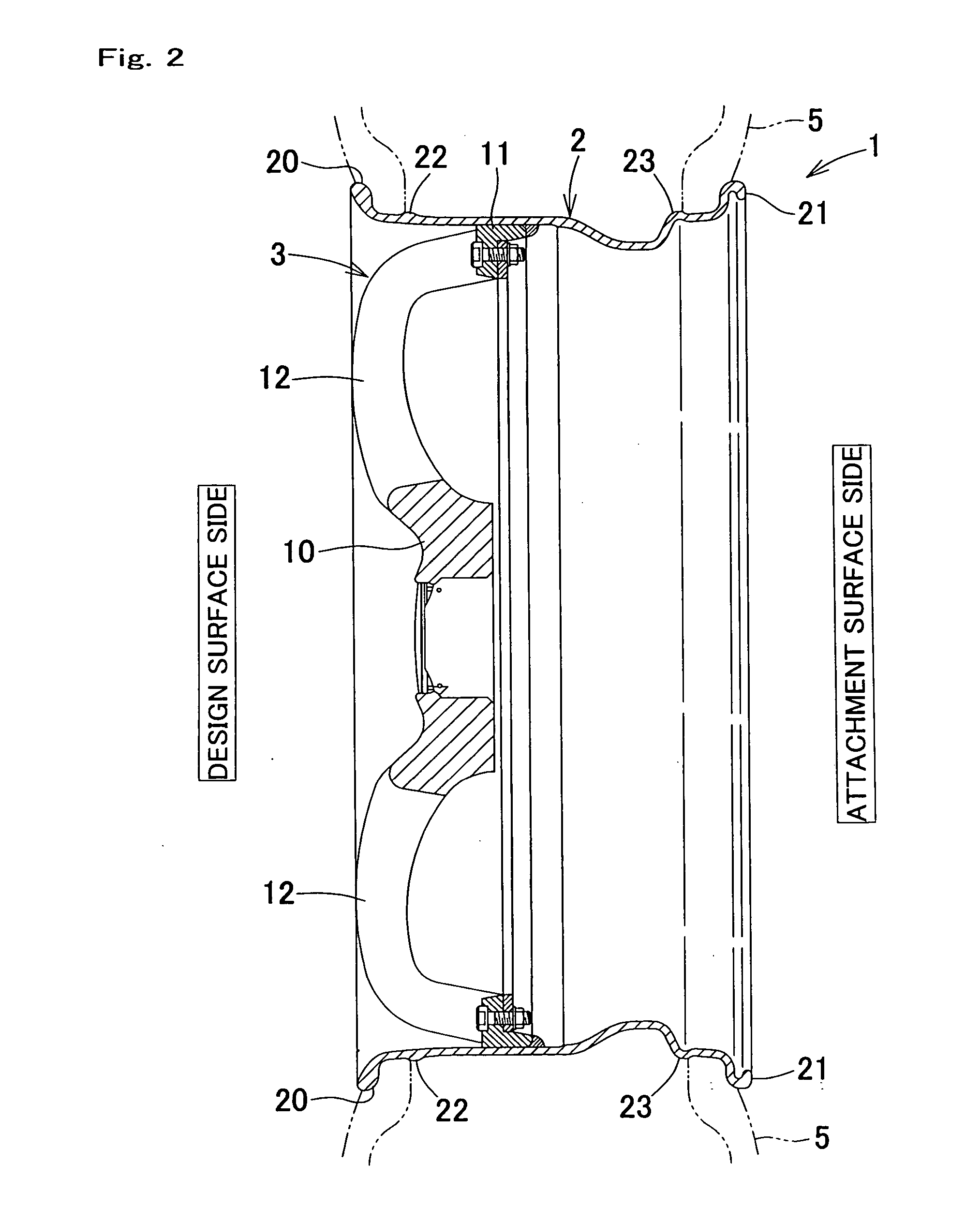
[0029] As is shown in FIGS. 1 and 2, the vehicle wheel 1 is a two-piece type wheel, and comprises a substantially cylindrical rim 2, and a disk 3 which is disposed on the inside of the rim 2, and whose outer end part is fastened to the inner circumferential surface of the rim 2 by welding.

[0030] The disk 3 is molded as an integral unit by casting, press-molding, forging or the like using a light-weight metal material such as an aluminum alloy or the like, and comprises an attachment part 10 which is used to attach the disk to a wheel supporting member (not shown in the figures) disposed on the vehicle body side, an annular ring part 11 which is disposed so as to surround the attachment part 10, and spoke parts 12 that connect the attachment part 10 and ring part 11. The ring part 11 is fastened by welding to the inner circumferential surface of the rim 2, so that this ring ...


PUM

PropertyMeasurementUnit
thicknessaaaaaaaaaa
curvature radiusaaaaaaaaaa
shapeaaaaaaaaaa

Abstract

The present invention provides a wheel and manufacturing method of the same which make it possible to prevent the formation of indentations along the hump parts in the inner circumferential surface of the rim. In a wheel which comprises a cylindrical rim consisting of a rolled metal plate, and in which hump parts that are used to lock the inner circumferential edge part of the tire are disposed circumferentially so that these hump parts protrude to the outside in the vicinity of the end part of the outer circumferential surface of the rim on at least the design surface side, the outer hump part is formed to have an increased thickness by damming so that this outer hump part protrudes outward while the inner circumferential surface of the rim that corresponds to the outer hump part is formed into a flat circumferential surface.

Description

BACKGROUND OF THE INVENTION [0001] 1. Field of the Invention [0002] The present invention relates to a wheel and a method of manufacturing the same. [0003] 2. Description of the Related Art [0004] One-piece type wheels which are integrally molded by casting, two-piece type wheels with a construction that is split into two parts, i. e., a rim and a disk, and three-piece type wheels with a construction that is split into three parts, i. e., an inner rim, and outer rim and a disk, are widely used as vehicle wheels that consist of light alloys such as aluminum alloys or the like. [0005] In the case of two-piece type wheels and three-piece type wheels, wheels in which the disk is manufactured by casting or forging, and the rims are constructed using rolled metal plates have been adapted for practical use. Rims that are used in such cases include products in which band form rolled metal plates are rolled up into a cylindrical shape, both ends are welded, and the produced is molded into a ...

Claims


Application Information

Patent Timeline
03 Nov 2005
Publication
US20050241740A1
IPC
B21D53/30; B60B21/00; B60B3/04; B60B21/02; B60B21/10; B60C15/02
CPC
B60B3/002; B60B3/10; B60B21/028; Y10T29/49529; B60B23/10; B60B25/002; Y10T29/49501; B60B21/104
Inventors
TANAKA, TAKESHI