AI technical title is built by PatSnap AI team. It summarizes the technical point description of the patent document.
a technology of kidney dialysis and kidney, applied in the direction of filtration separation, separation process, instruments, etc., can solve the problem that nonetheless have certain limitations
Inactive Publication Date: 2005-11-03
BAXTER INT INC
View PDF99 Cites 160 Cited by
Summary
Abstract
Description
Claims
Application Information
AI Technical Summary
This helps you quickly interpret patents by identifying the three key elements:
Problems solved by technology
Method used
Benefits of technology
Problems solved by technology
While machines according to the prior art provide a number of advantageous features, they nonetheless have certain limitations.
Method used
Image
Click on the blue label to locate the original text in one second.
Reading with bidirectional positioning of images and text.
Examples
Embodiment Construction
Hydraulic Circuit
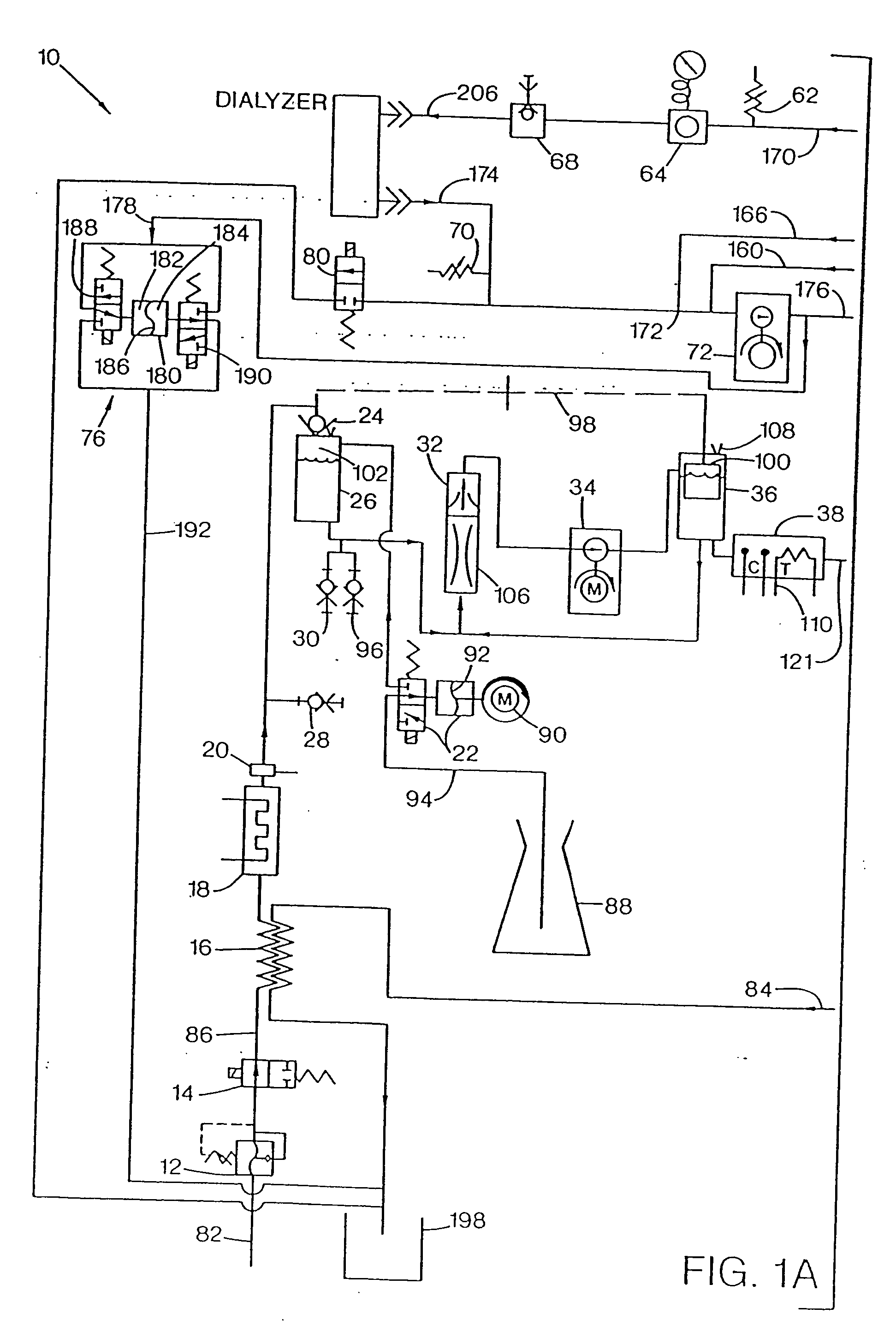
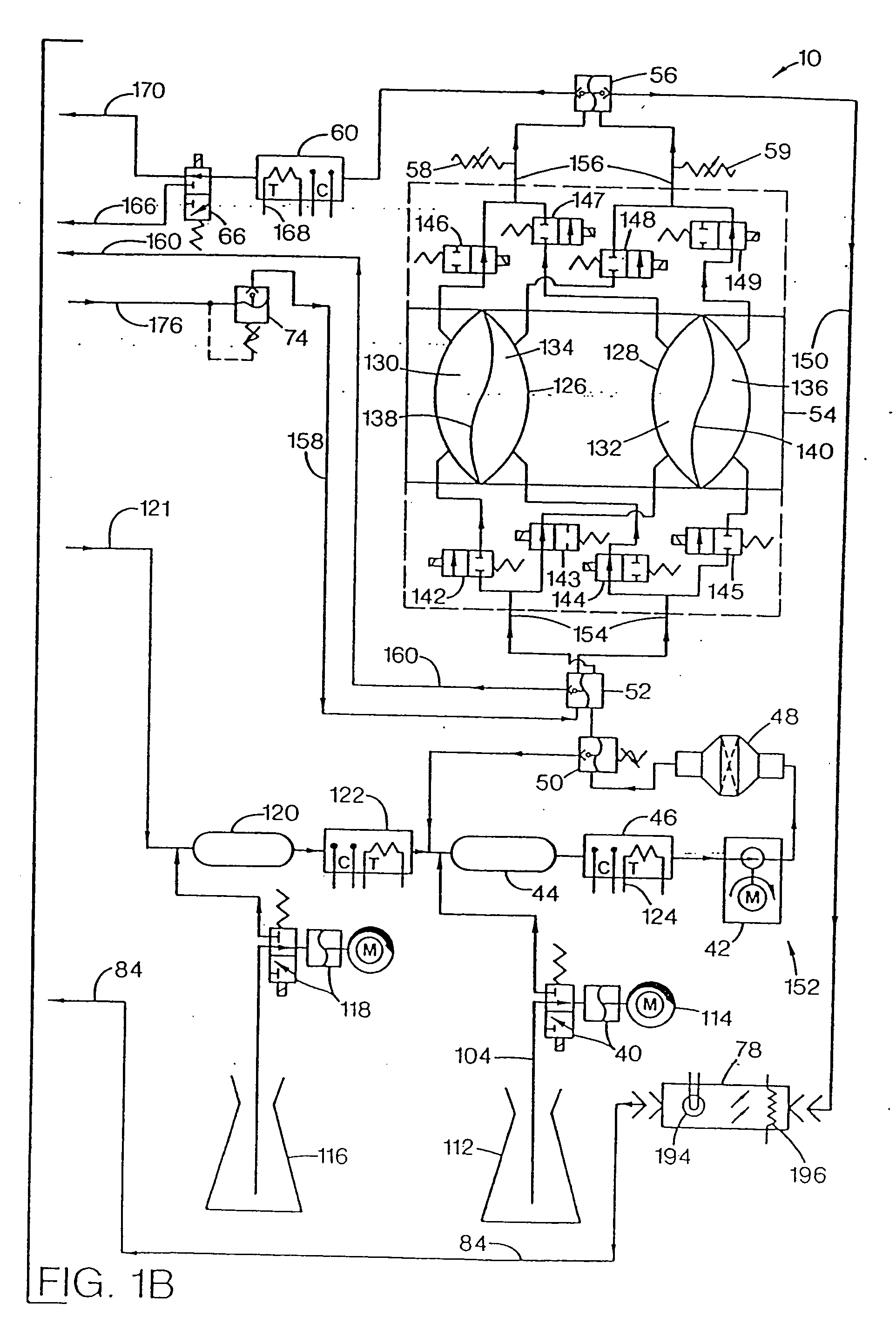
[0017] A hydraulic circuit 10 representing a preferred embodiment of an improved hemodialysis machine according to the present invention is illustrated in FIG. 1. The hydraulic circuit 10 is comprised of the following principal components: an incoming water pressure regulator 12, a water on / off valve 14, a heat exchanger 16, a heater 18, a safety thermostat 20, an “A” concentrate pump 22, a supply valve 24, an air gap chamber 26, an “A” rinse fitting 28, a “B” rinse fitting 30, a deaeration sprayer 32, an air removal pump 34, a vented air trap 36, an “A” conductivity probe 38, a “B” concentrate pump 40, a supply pump 42, a “B” mix chamber 44, a “B” conductivity probe 46, a dialysate filter 48, a supply regulator 50, an input pressure equalizer 52, a flow equalizer 54, an output pressure equalizer 56, end-of-stroke sensors 59, a dialysate conductivity probe 60, a pre-dialyzer flow sensor 62, a dialysate pressure transducer 64, a bypass valve 66, a dialysate sample p...
PUM
Property
Measurement
Unit
pressure
aaaaa
aaaaa
temperature
aaaaa
aaaaa
pressure
aaaaa
aaaaa
Abstract
A number of improvements relating to methods and apparatuses for kidney dialysis are disclosed. These include checking of dialysate bypass status using flow measurement; using a flow sensor to confirm the absence of ultrafiltration during bypass; automatic testing of ultrafiltration function by removal of a discrete volume from a portion of the dialysate flow path coupled with a pressure test of that part of the flow path; using a touch screen user interface; bar graph profile programming of ultrafiltration, sodium, and bicarbonate parameters; using a RAM card to upload treatment instructions to, and to download treatment data from, the machine; automatic setting of proportioning mode (acetate or bicarbonate) based on connections of concentrate lines; predicting dialysate conductivity values based on brand and formulation of concentrates; minimizing no-flow dead time between dialysate pulses; initiating operation in a timed mode from a machine power-off condition; preserving machine mode during machine power-fail condition; calibration scheduling and reminding; automatic level adjusting; and blood leak flow rate detecting.
Description
RELATED APPLICATIONS [0001] This application is a continuation of U.S. patent application Ser. No. 09 / 711,240 filed on Nov. 13, 2000, now pending, which is a continuation of U.S. patent application Ser. No. 09 / 067,922 filed on Apr. 28, 1998, now abandoned, which is a continuation of U.S. patent application Ser. No. 08 / 479,688, filed on Jun. 7, 1995, now U.S. Pat. No. 5,744,027, which is a divisional of U.S. patent application Ser. No. 08 / 122,047, filed on Sep. 14, 1993, now U.S. Pat. No. 5,486,286, which is a divisional of U.S. patent application Ser. No. 07 / 688,174, filed on Apr. 19, 1991, now U.S. Pat. No. 5,247,434.FIELD OF THE INVENTION [0002] The present invention relates to improvements in kidney dialysis machines. BACKGROUND OF THE INVENTION [0003] Kidney dialysis machines are well known in the art and are illustrated, for example, in U.S. Pat. Nos. 3,598,727, 4,172,033, 4,267,040, and 4,769,134. [0004] While machines according to the prior art provide a number of advantageou...
Claims
Application Information
Patent Timeline
Application Date:The date an application was filed.
Publication Date:The date a patent or application was officially published.
First Publication Date:The earliest publication date of a patent with the same application number.
Issue Date:Publication date of the patent grant document.
PCT Entry Date:The Entry date of PCT National Phase.
Estimated Expiry Date:The statutory expiry date of a patent right according to the Patent Law, and it is the longest term of protection that the patent right can achieve without the termination of the patent right due to other reasons(Term extension factor has been taken into account ).
Invalid Date:Actual expiry date is based on effective date or publication date of legal transaction data of invalid patent.
Patent Type & AuthorityApplications(United States)
InventorCONNELL, MARK E.BEDIENT, ROBERT A.ELSEN, RAYMONDHOGARD, MICHAEL E.JOHNSON, HARLEY D.KELLY, THOMAS D.LONG, JEAN MCEVOYPETERSON, BRUCE A.PRESTON, WILLIAM G. JR.SMEJTEK, DALIBOR J.

