DC-DC high frequency boost converter

Active Publication Date: 2005-11-03
TEXAS INSTR INC
View PDF7 Cites 11 Cited by
  • Summary
  • Abstract
  • Description
  • Claims
  • Application Information

AI Technical Summary

Benefits of technology

[0009] The present invention provides a DC-DC high frequency boost converter with a simplified circuit layout and a fast zero-current detection.
[0010] Specifically a DC-DC high frequency boost converter with a supply voltage input, a boosted voltage output and an inductor and a rectifying device connected in series between the supply voltage input and the boosted voltage output is provided. The converter comprises a switch which is connected between ground and a connection node of the inductor and the rectifying device. The converter comprises further a control circuit for controlling this switch and a zero inductor current detection circuit that compares a voltage on the connection node with a reference voltage and provides a zero inductor current indication when both voltages are equal. With the proposed converter, the node voltage instead of the output current is monitored. Monitoring the output current by measuring the voltage drop across a series-connecte

Problems solved by technology

At high switching frequencies (>1 MHz) the impact of this delay δ gets too high and results for example in efficiency loss, if the comparator signal is used to switch into a power save mode.
Furt

Method used


Image

  • DC-DC high frequency boost converter
  • DC-DC high frequency boost converter
  • DC-DC high frequency boost converter

Examples


Example

DETAILED DESCRIPTION OF THE DRAWINGS

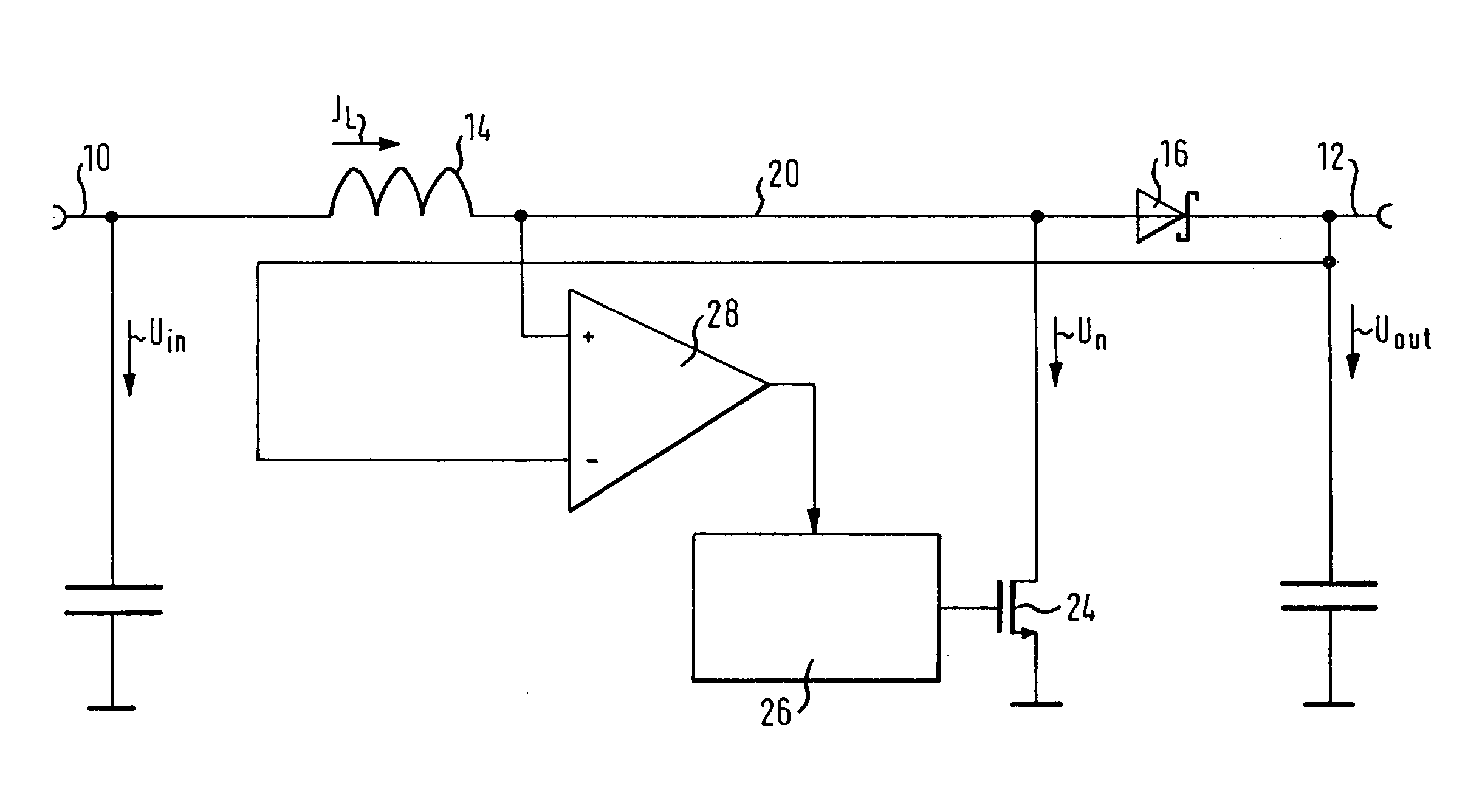
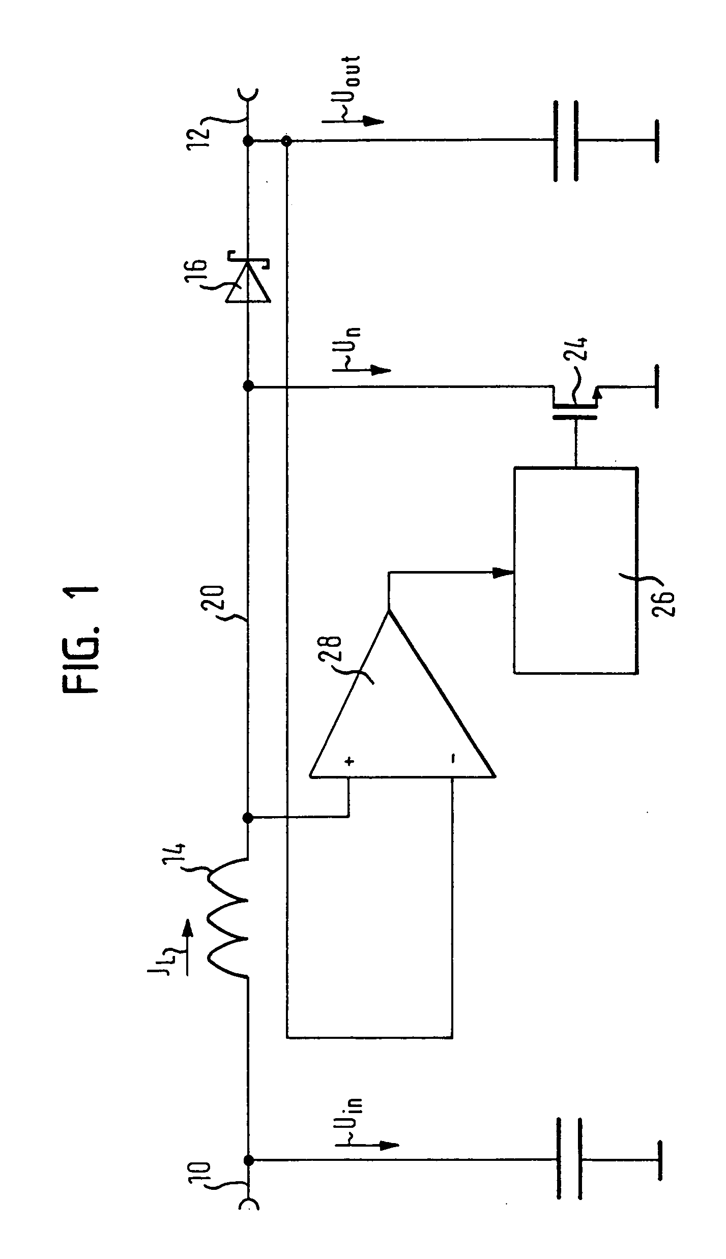
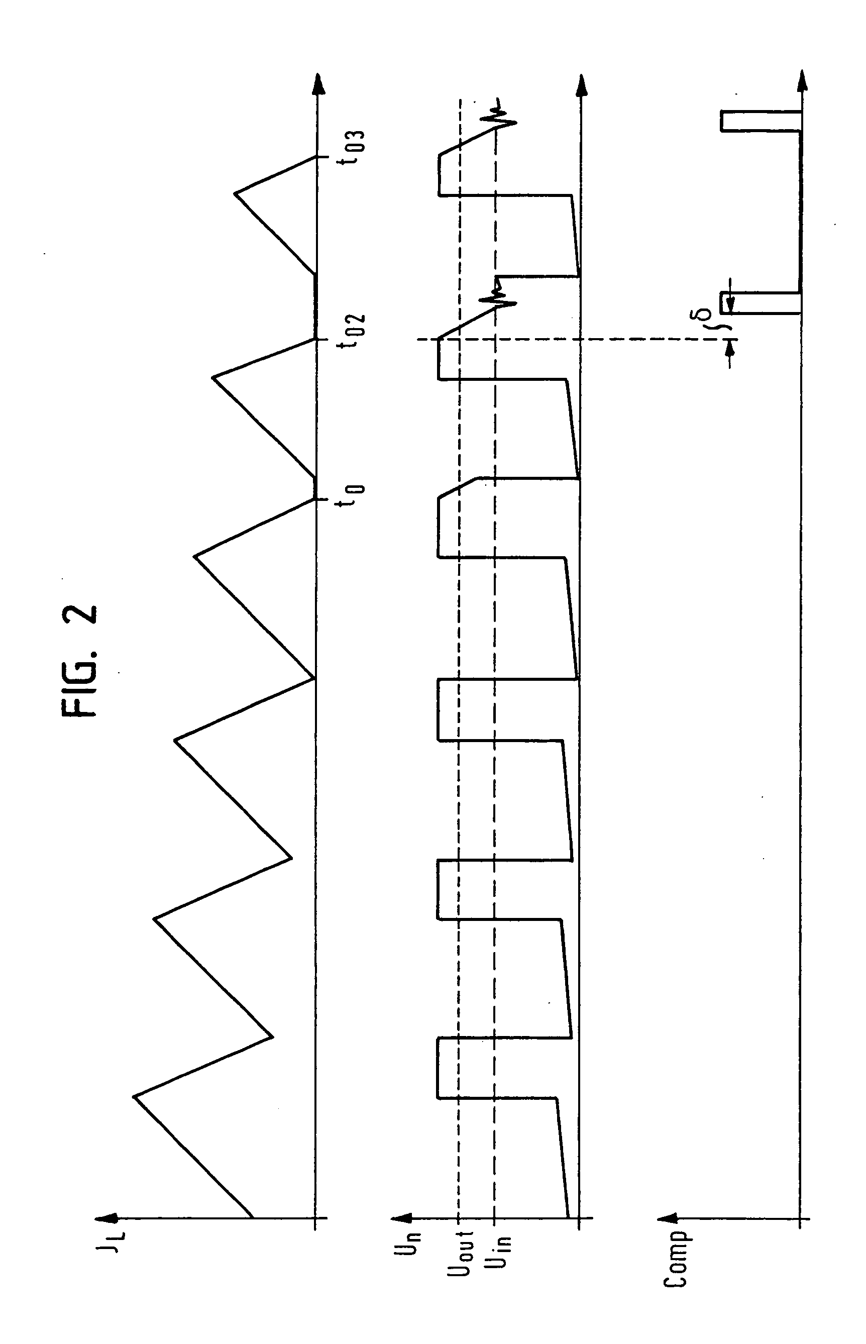
[0016] Referring now to FIG. 3, there is shown a schematic of a DC-DC high frequency boost converter according to the invention. The converter comprises a supply voltage input 110, a boosted voltage output 112, a series circuit of an inductor 114 and a diode 116, a load capacitor 118 and a power switch 124. The converter further comprises a control circuit 126 for controlling the power switch 124 and a zero inductor current detection circuit 128.

[0017] The supply voltage input 110 is buffered with a source capacitor 130 connected between the input 110 and ground. The inductor coil 114 is connected with one end to the supply voltage input 110 and with the other end to the anode of the rectifying device 116 which is constituted by a schottky diode in this embodiment. The cathode of the schottky diode 116 is connected to a boosted voltage output 112 which is also connected to the load capacitor 118. The connection between the inductor 114 and the d...


PUM


Abstract

A DC-DC high frequency boost converter with a supply voltage input (110), a boosted voltage output (112), a series circuit of an inductor (114) and a rectifying device (116) connected in series between said supply voltage input (110) and said boosted voltage output (112), has a switch (124) connected between ground and a connection node (120) of said inductor (114) and said rectifying device (116). A control circuit (126) is provided for controlling said switch (124), and a zero inductor current detection circuit (128) is provided that compares a voltage (Un) on said connection node (120) with a reference voltage (Uref) and provides a zero inductor current indication (Comp) when both voltages are equal.

Description

CROSS REFERENCE TO RELATED APPLICATIONS [0001] This application claims priority under 35 USC § 119 of German Application Serial No. 10 2004 021437.9, filed Apr. 30, 2004. FIELD OF THE INVENTION [0002] The present invention relates to a DC-DC high frequency boost converter with a supply voltage input, a boosted voltage output, a series circuit of an inductor and a rectifying device connected between the supply voltage input and the boosted voltage output, a switch connected between ground and a connection node of the inductor and the rectifying device, and a control circuit for controlling the switch. BACKGROUND OF THE INVENTION [0003] In such boost converters that operate in voltage mode at a fixed frequency, the output voltage is a function of the duty cycle which depends on the ratio between the on-time and the off-time of the switch. As long as the load current is high enough, the converter can operate in continuous mode: the inductor current increases when the switch is closed, ...

Claims


Application Information

Patent Timeline
IPC IPC(8): H02M3/156
CPCH02M3/156Y02B70/16H02M2001/0032H02M2001/0009Y02B70/10H02M1/0032H02M1/0009
Inventor REITHMAIER, STEFAN
Owner TEXAS INSTR INC
Why Eureka
Try Eureka