Fluorescent lamp driving circuit

a technology of driving circuit and fluorescent lamp, which is applied in the direction of light sources, instruments, electrical equipment, etc., can solve the problems of complex circuit design and increase production cost, and achieve the effects of reducing circuit cost, reducing the number of pins, and reducing the requirement of electronic components

Inactive Publication Date: 2011-06-21
NIKO SEMICON
View PDF11 Cites 8 Cited by
  • Summary
  • Abstract
  • Description
  • Claims
  • Application Information

AI Technical Summary

Benefits of technology

[0008]The object of the present invention is to effectively reduce the number of pins in a PWM controller and lessen the required electronic components, in order to reduce circuit cost as well as simplify circuit layout.
[0012]In summary, the present invention provides a fluorescent lamp driving circuit, in the case of simultaneously driving multiple lamps, whose controller needs one pin for receiving the current detection signal to achieve the feature of feedback control, and another pin for receiving the protection feedback signal to offer protection control, as a result, the number of pins in the controller and the corresponding electronic components required for the purposes of feedback and protection are reduced, and circuit design is simplified as well.

Problems solved by technology

Due to the trend of large-scaled liquid crystal panel, the number of CCFLs in the backlight module needed to be driven increases accordingly, conventional driving circuit applying single PWM controller and single resonant module for driving single lamp may result in complexity in circuit design as well as increasing of production cost.

Method used


Image

  • Fluorescent lamp driving circuit
  • Fluorescent lamp driving circuit
  • Fluorescent lamp driving circuit

Examples


first embodiment

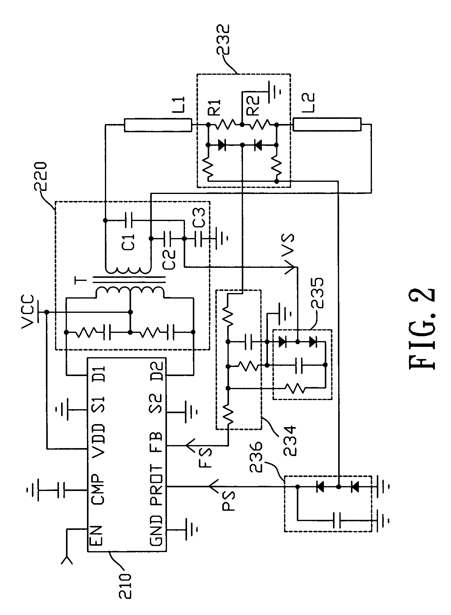
[0022]Refer now to FIG. 2, which shows a circuit diagram of the multi-lamp driving circuit in accordance with the present invention, the multi-lamp driving circuit has a controller 210, a resonant module 220, a lamp module, and a detection device. The lamp module has lamps L1, L2. The detection device has a detection part 232, a current detection feedback part 234, a voltage detection feedback part 235, and a protection detection feedback part 236. The resonant module 220 has a primary side and a secondary side. The primary has a transformer T and resonant capacitors C1˜C3. The primary side of the transformer T has two connection ends and a central tap end, wherein the central tap end is connected to an input voltage source VCC, and the two connection ends are respectively connected to the pins D1, D2 of the controller 210. In this way, the resonant module 220 may convert the power of the input voltage from the input voltage source VCC received on the primary side into an AC signal ...

third embodiment

[0026]Refer now to FIG. 4, a circuit diagram of the multi-lamp driving circuit in accordance with the present invention is shown. The multi-lamp driving circuit of the present embodiment comprises a controller 410, a resonant module 420, a lamp module, and a detection device. The lamp module has lamps L1˜L4. The detection device includes two detection parts 432a, 432b, a current detection feedback part 434, and a protection detection feedback part 436. The resonant module 420 has a primary side and a secondary side and primarily has a transformer T and resonant capacitors C1˜C3 for converting the power received on the primary side into an AC signal outputted on the secondary side. The secondary side of the transformer T has two windings. The lamp module has a plurality of lamps L1˜L4, wherein lamps L1, L2 are coupled in series to a winding on the secondary side of the transformer T, and lamps L3, L4 are coupled in series to the other winding on the secondary side of the transformer ...


PUM


Abstract

A fluorescent lamp driving circuit is provided. The fluorescent lamp driving circuit collects a pulse-width-modulation and a MOS switch in a single package. The pulse-width-modulation for driving multiple lamps only needs two pins to achieve feedback control and protection control. Thereby the pins required by the pulse-width-modulation are decreased substantially, and the electronic elements needed for feedback and protection control are also reduced, and the overall circuit design is simplified.

Description

BACKGROUND OF THE INVENTION[0001]1. Field of the Invention[0002]The present invention is related to a fluorescent lamp driving circuit; in particular, to a multi-lamp driving circuit with built-in MOSFET (Metal Oxide Semiconductor Field Effect Transistor).[0003]2. Description of Related Art[0004]A backlight module of a liquid crystal display uses high-frequency sinusoidal-wave power supply to supply power as the energy required for lighting the Cold Cathode Fluorescent Lamp (CCFL), therefore it is demanded to employ DC / AC inverters to achieve the purpose of energy conversion. An ordinary CCFL driving circuit uses a resonant module to convert a DC voltage into an AC voltage to drive a CCFL to light up. The driving voltage and the driving current of the CCFL are detected by the voltage and current detection circuits. A Pulse-Width-Modulation (PWM) controller receives the generated voltage detection signal and current detection signal for the purposes of stabilizing the illumination of...

Claims


Application Information

Patent Timeline
Patent Type & Authority Patents(United States)
IPC IPC(8): H05B41/36
CPCH05B41/3925H05B41/2855
Inventor WANG, CHEN-HSUNG
Owner NIKO SEMICON
Why Eureka
Try Eureka