Eureka AIR delivers breakthrough ideas for toughest innovation challenges, trusted by R&D personnel around the world.

Light emitting device and information processing apparatus

Active Publication Date: 2005-11-03
PANASONIC CORP
View PDF7 Cites 3 Cited by
  • Summary
  • Abstract
  • Description
  • Claims
  • Application Information

AI Technical Summary

Benefits of technology

[0026] Thus, the invention described herein makes possible the advantages of providing a light emitting device that meets a recording / reproducing performance of a recording medium with a plurality of kinds of different specifications, using a light emitting device with a plurality of light sources arranged within the same housing, with a feature of making an angle of radiation along the horizontal direction of light from a light source, used for an optical system having a relatively small optimum optical magnification, narrower than an angle of radiation along the horizontal direction of light from a light source used for an optical system having a relatively large optimum optical magnification.

Problems solved by technology

However, making the fc / fo much smaller reduces the rim strength causing some adverse effects such as making the diameter of the focusing spot become larger, dropping signal quality of the reflected light from the recording medium and not obtaining sufficient apparatus performance.
Accordingly, when the optimum fc / fo is different, such as the optical system for DVD recording and the optical system for CD recording, there is a problem that a CD high-speed recording performance and recording / reproducing performance resulting from a focusing performance of a focusing spot for DVD are not compatible.
Specifically, when a plurality of light sources use a light emitting device arranged within a same housing and optical systems having different optimum optical magnifications (fc / fo), such as the ones used for an optical system for DVD recording and an optical system for CD recording, are composed of identical optical systems, the conventional technique can not obtain an optimum fc / fo for each optical system.
Therefore, when an optical magnification is made to a value close to the optimum fc / fo for an optical system for DVD recording, the efficiency from a light source of a CD becomes lower and a high-speed recording performance can not be obtained.
On the other hand, when an optical magnification is made to a value close to the optimum fc / fo for an optical system for CD recording, the rim strength of light incident on an objective lens from a light source for DVD drops, a focusing performance of the focusing spot of DVD drops and therefore, the desired DVD record-reproducing performance is not able to be obtained.

Method used


Image

  • Light emitting device and information processing apparatus
  • Light emitting device and information processing apparatus
  • Light emitting device and information processing apparatus

Examples


Embodiment Construction

[0033] In an optical system using a light emitting device arranged within the same housing, the object of making the performance of an information processing apparatus having different optimum optical magnifications, which are compatible, is realized with the same optical feature as in the conventional apparatus.

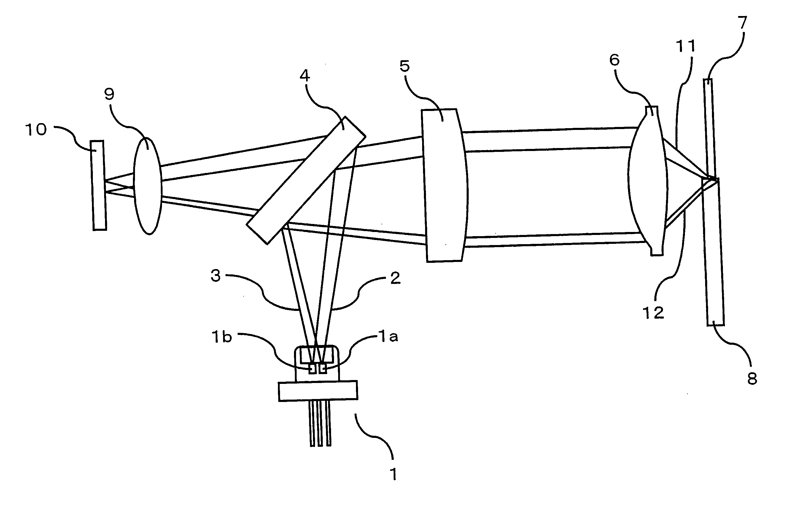
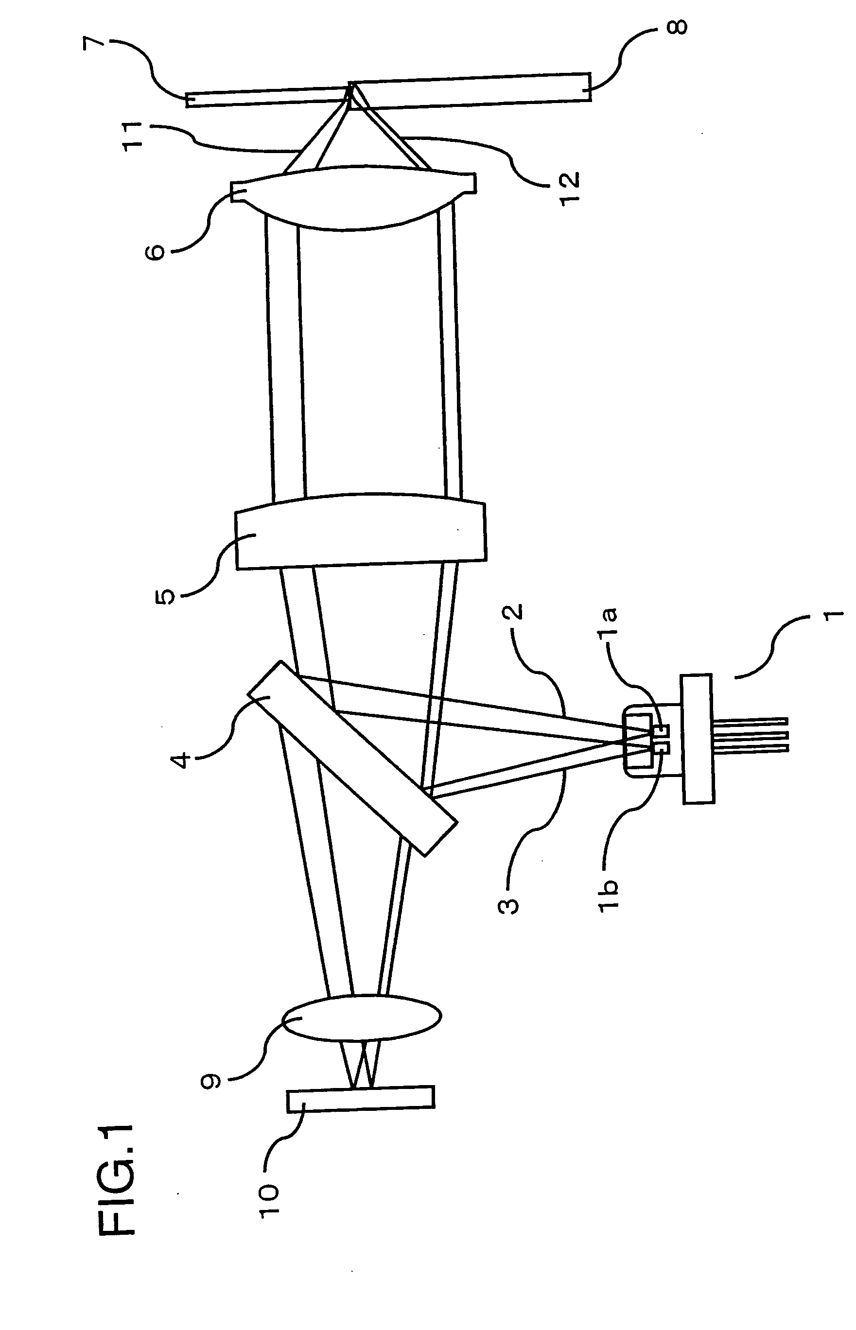
[0034] Herein below, one embodiment of the present invention is explained with reference to the figures. Like reference numbers refer to like or equivalent parts throughout the figures. FIG. 1 is a view of the relevant parts of an information processing apparatus according to a first embodiment of the present invention. Light sources 1a and 1b are arranged to provide two wavelengths within light source device 1. In operation the light emitted from the light sources 1a and 2b is reflected by the recording media 7 and 8 and enters a light detector 10 in the same manner as in the conventional example, therefore, the detailed description thereof is omitted.

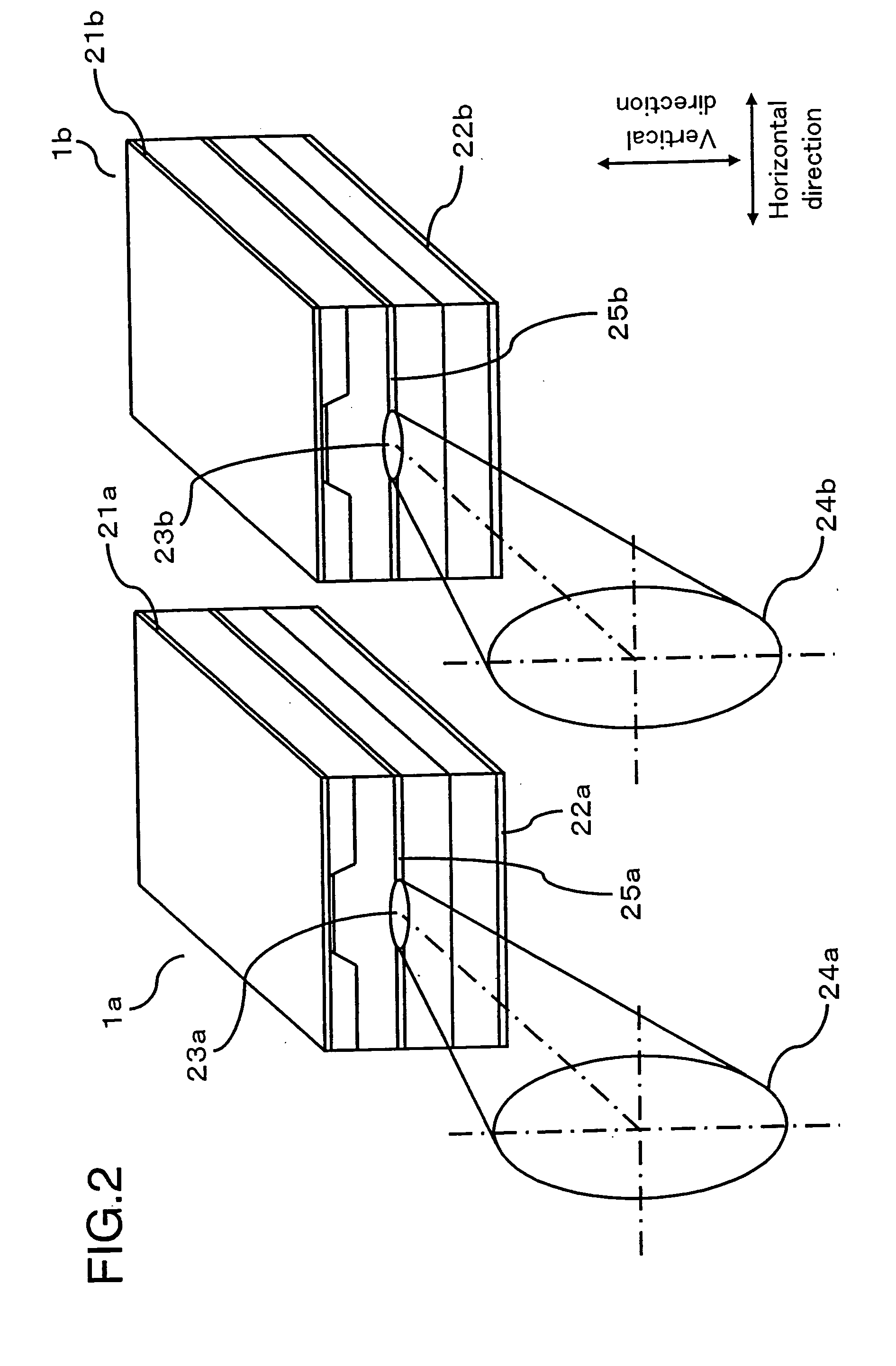
[0035]FIG. 2 is an e...


PUM


Abstract

A light emitting device according to the present invention includes: a first light source for emitting light having a first wavelength; and a second light source for emitting light having a second wavelength which is different from the first wavelength, wherein the first light source and the second light source are arranged in the same housing, and a relationship of θh1>θh2 is satisfied, where θh1 denotes an angle (full-width-half-maximum) of radiation of the light emitted from the first light source in the horizontal direction, and θh2 denotes an angle (full-width-half-maximum) of radiation of the light emitted from the second light source in the horizontal direction.

Description

BACKGROUND OF THE INVENTION [0001] 1. Field of the Invention [0002] The present invention relates to a light emitting device and an information processing apparatus for optical recording / reproduction of information. [0003] 2. Description of the Related Art [0004] When a single apparatus is used to record / reproduce information for a plurality of recording mediums which have different recording density of information, in general, an information processing apparatus having a plurality of light sources is used. For example, for recording mediums such as a Digital Versatile Disc (hereinafter referred to as “DVD”) and a compact disk (hereinafter referred to as “CD”) which have different formats, a technique for recording / reproduction of information using a single apparatus having two light sources with different wavelengths has been developed and is practically used. [0005] A light emitting device is used in many practical apparatuses having a plurality of light sources. Conventionally, s...

Claims


Application Information

Patent Timeline
IPC IPC(8): G01N21/86G01V8/00G01V8/14G11B7/125
CPCG11B7/127G01V8/14G11B7/1275
Inventor TAKAHASHI, YUUICHIMOMOO, KAZUO
Owner PANASONIC CORP
Why Eureka
Eureka Blog
Learn More