Encoding circuit

a technology of encoding circuit and coding circuit, which is applied in the field of encoding circuit, can solve the problems that other techniques, such as dpcm and prediction coding, cannot achieve high compression ratio, and achieve the effect of high compression ratio

Inactive Publication Date: 2005-11-03
SANYO ELECTRIC CO LTD
View PDF12 Cites 18 Cited by
  • Summary
  • Abstract
  • Description
  • Claims
  • Application Information

AI Technical Summary

Problems solved by technology

However, as can be imagined from the basic principle thereof, both the MPEG and DV formats require a large encoding circuit, while other techniques which do not require large scale encoding circuits, such as DPCM and prediction coding, cannot be expected to achieve a high compression ratio.

Method used


Image

  • Encoding circuit
  • Encoding circuit
  • Encoding circuit

Examples


Embodiment Construction

[0016] A preferred embodiment of the present invention will now be described with reference to FIGS. 1-7.

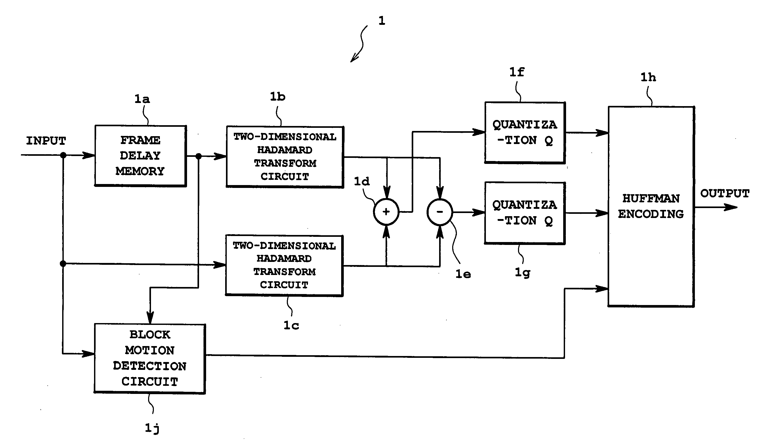
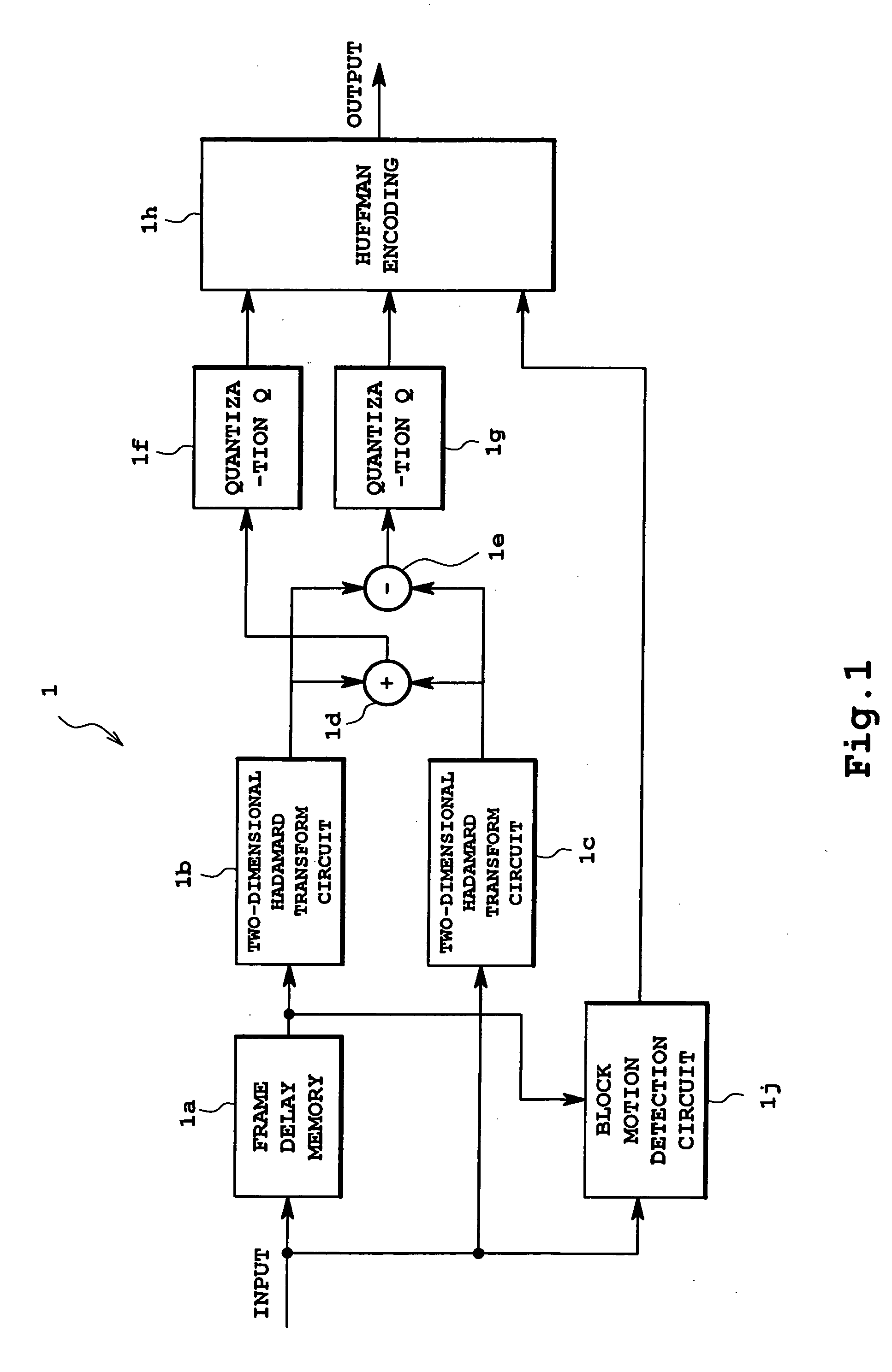
[0017]FIG. 1 is a block diagram showing an encoding circuit 1. A video signal supplied thereto is a digitized video signal (such as luminance / color-difference signals or RGB signals). A first Hadamard transform circuit 1b of the encoding circuit 1 receives the video signal delayed via a frame delay memory 1a, while a second Hadamard transform circuit 1c directly receives the video signal without being routed through the frame delay memory 1a.

[0018] The Hadamard transform circuits 1b and 1c divide the supplied video signal into blocks of a predetermined size, and calculate a two-dimensional Hadamard transform component for each block. The operation performed here is an operation for a Hadamard matrix having the rows (m) and the columns (n), and each component of the matrix will be either +1 or −1. For example, when each video signal is divided into a block of “m” rows and “n” co...


PUM


Abstract

Blocks in two different frames are subjected to Hadamard transform by first and second Hadamard transform circuits, and a sum component and a difference component are calculated for the components of the two blocks corresponding to each other to perform three-dimensional Hadamard transform, so that detection is made as to whether or not these blocks include a motion. While the sum component and the difference component are encoded for the block determined as including a motion, a motion detection result, rather than the difference component, is encoded for the block determined as including no motion. As a result, a high compression ratio can be achieved in video encoding with a small-scale circuit.

Description

CROSS-REFERENCE TO RELATED APPLICATIONS [0001] The entire disclosure of Japanese Patent Application Nos. 2004-332082 and 2004-127147 including specification, claims, drawings, and abstract is incorporated herein by reference. BACKGROUND OF THE INVENTION [0002] 1. Field of the Invention [0003] The present invention relates to an encoding circuit for achieving a high compression ratio in encoding video signals. [0004] 2. Description of the Related Art [0005] The MPEG technique, one of the commonly employed conventional encoding techniques, is based on the principal of orthogonal transformation through inter-frame prediction coding and DCT (discrete cosine transform) and utilizes motion vectors to strengthen correlation between frames, thereby improving prediction accuracy and further enhancing the compression ratio. Another compression method for a DVC (digital video cassette) is based on DCT and an encoding method in which groups of encoding blocks are provided and such groups are co...

Claims


Application Information

Patent Timeline
IPC IPC(8): H04N19/50H03M7/30H04N7/12H04N19/105H04N19/136H04N19/196H04N19/42H04N19/423H04N19/503H04N19/51H04N19/60H04N19/61H04N19/91
CPCH04N19/176H04N19/122H04N19/137H04N19/124H04N19/60H03M7/30
Inventor EBARA, MASAMITAKAE, OSAMU
Owner SANYO ELECTRIC CO LTD
Why Eureka
Try Eureka