Dental finishing device

Inactive Publication Date: 2005-11-03
SS WHITE BURS
View PDF10 Cites 11 Cited by
  • Summary
  • Abstract
  • Description
  • Claims
  • Application Information

AI Technical Summary

Problems solved by technology

This may result in the dentist using the finishing strip on one portion of the tooth and then inserting, positioning and using the finishing strip again on another portion of the tooth that may have been initially missed by the flared out portion of the finishing strip.

Method used


Image

  • Dental finishing device
  • Dental finishing device
  • Dental finishing device

Examples


Embodiment Construction

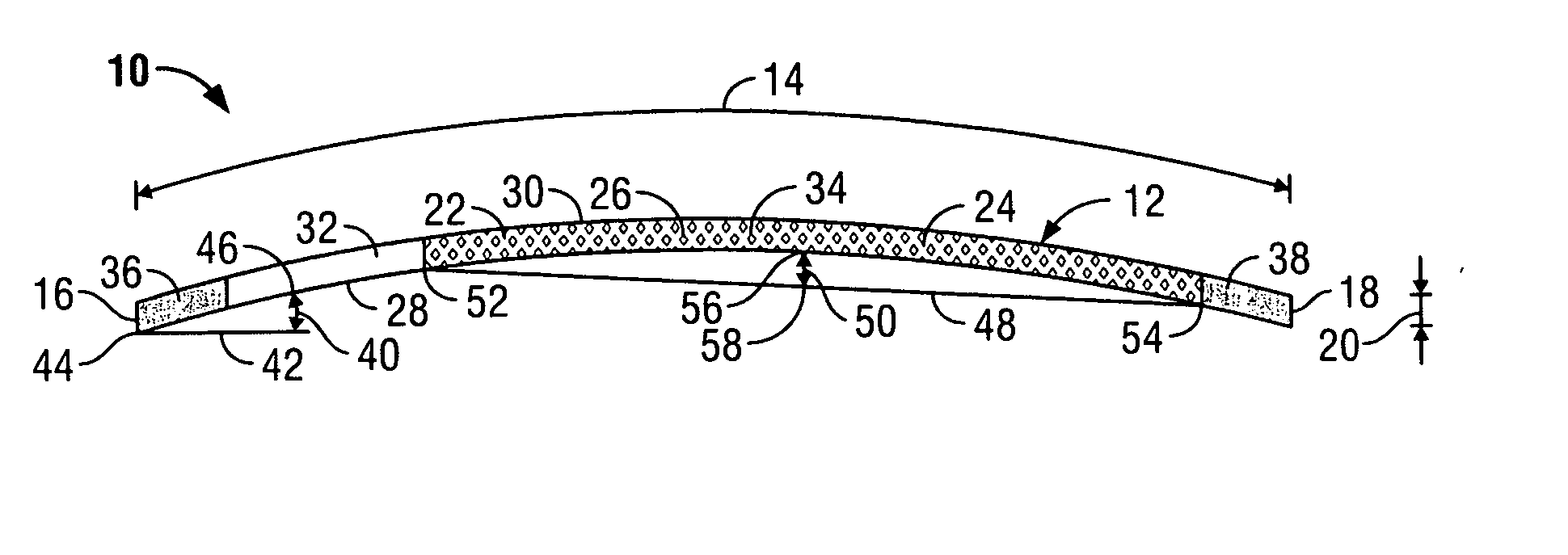
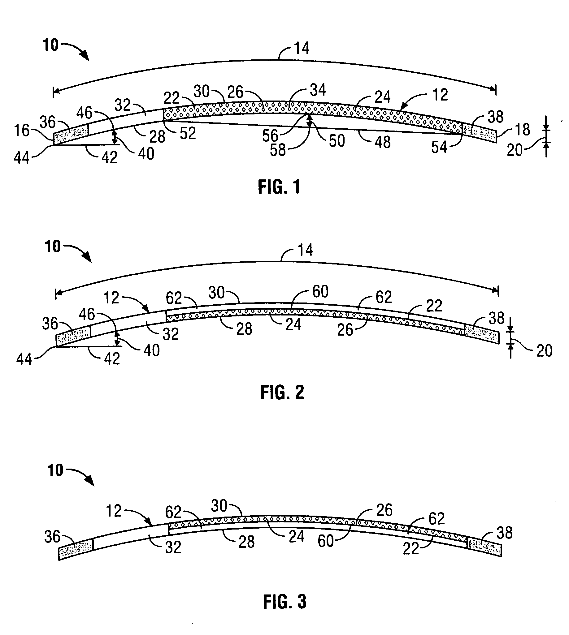
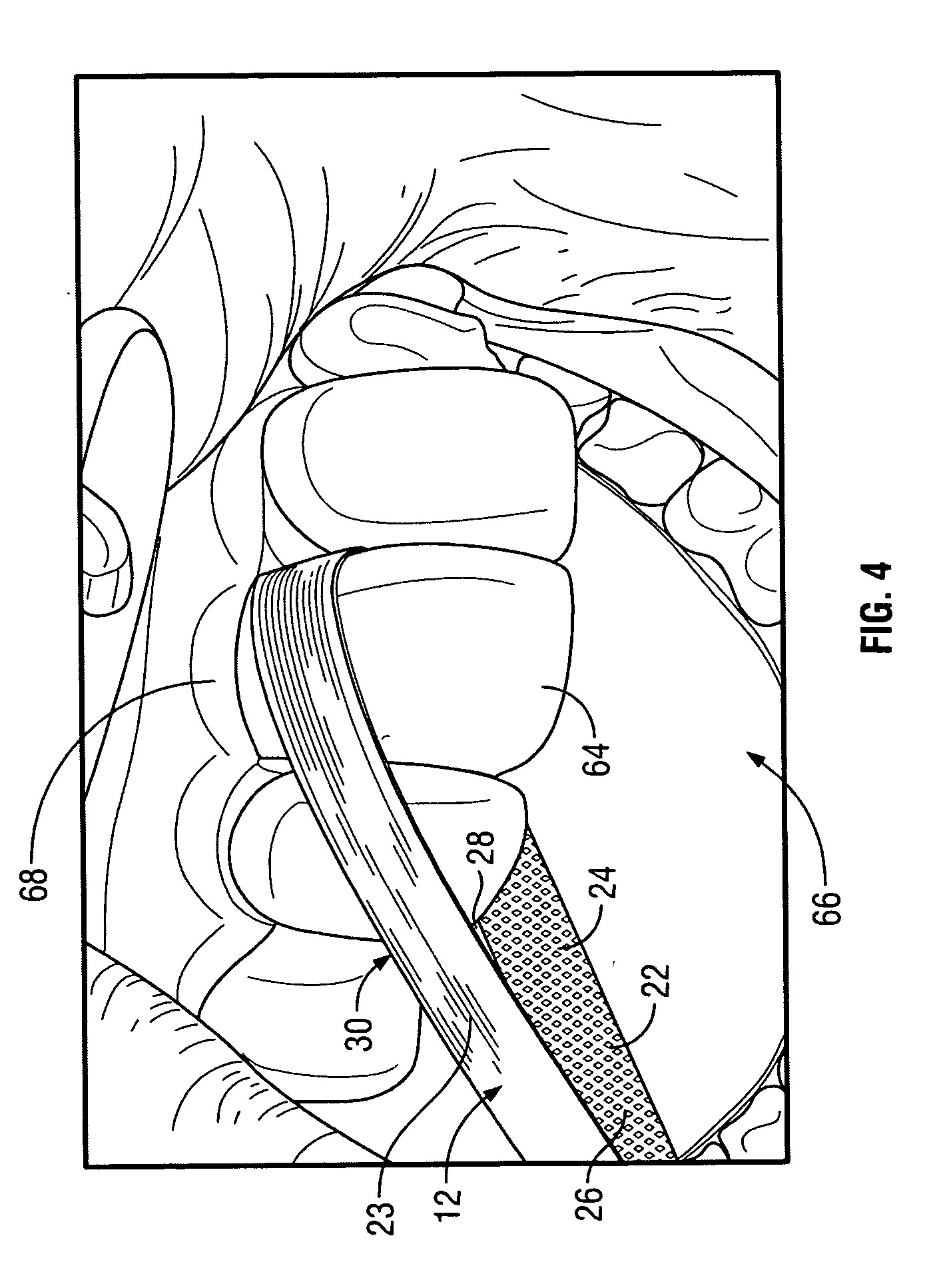
[0008] Referring to FIG. 1, dental finishing device 10 for the abrasion of a tooth, a tooth filling material or any tooth restorative material is shown. The dental finishing device 10 has a thin elongated flexible strip 12 with a length 14 extending between two ends 16, 18 and has a width 20 as seen in FIG. 1. The elongated flexible strip 12 has a pair of elongated surfaces, a working surface 22 as seen in the example of FIG. 1 and a smooth backing surface 23 (FIG. 4). The elongated flexible strip 12 may selectively be comprised of a corrosion-resistant metal such as stainless-steel, titanium or other metals, or alternatively plastic.

[0009] An abrasive coating 24, as seen in FIG. 1, on the working surface 22 forms an abrasive portion 26 on the elongated flexible strip 12. The abrasive portion 26 on surface 22 of flexible strip 12 is used for finishing, polishing and / or reduction of a tooth or tooth filling material. The abrasive coating 24 generally will employ multiple grains of d...


PUM


Abstract

A dental finishing device for the finishing, polishing or reduction of a tooth or tooth filling material having an elongated flexible strip with a curved shape along the length of the flexible strip. An abrasive coating is disposed on the surface of the flexible strip forming an abrasive portion on the strip surface. An abrasive-free access portion is positioned adjacent to the abrasive portion and is positioned towards an end of the flexible strip. The flexible strip has a concave side and a convex side which extend along at least a portion of the length of the flexible strip.

Description

BACKGROUND OF THE INVENTION [0001] Dental finishing strips have been used for various dental procedures such as finishing, polishing and reduction of teeth, teeth filling material or teeth restorative material. Such finishing strips are generally flexible thin metal or plastic strips having diamonds or other abrasive materials disposed on one side or both side surfaces of the strip such that an active or abrasive region of the strip is formed. Certain finishing strips provide an access area without any abrasive material on the surface which is positioned in the middle or center of the strip dividing the strip into two separate abrasive regions whereby the strip is inserted between adjacent teeth of a patient through the non-abrasive access area. Once the finishing strip is positioned it is pulled through the teeth to allow the diamond material move across the surface of a tooth. For instance, a finishing strip may be used for removing excess material or contouring regions of a filli...

Claims


Application Information

Patent Timeline
Patent Type & Authority Applications(United States)
IPC IPC(8): A61C3/06
CPCA61C3/06
Inventor FREEDMAN, GEORGE
Owner SS WHITE BURS
Why Eureka
Try Eureka