Magnetic field sensor-based navigation system to track MR image-guided interventional procedures

a magnetic field sensor and navigation system technology, applied in the field of magnetic field sensor-based navigation system to track magnetic field sensor-based navigation system to determine the exact spatial position of the interventional device within three-dimensional spa

Inactive Publication Date: 2005-11-03
UNIVERSITY OF BASEL
View PDF5 Cites 80 Cited by
  • Summary
  • Abstract
  • Description
  • Claims
  • Application Information

AI Technical Summary

Problems solved by technology

The poor visibility and tractability of interventional devices, such as puncture needles, guidewires, catheters, and the like, is a major problem encountered during MRI guided interventional procedures.
While these interventional devices produce an excellent contrast in x-ray images, this is generally not the case during MR imaging.
In general, MR image contrast generated with passive visualisation methods has proven insufficient to determine the exact spatial position of an interventional device within three-dimensional space, especially when the interventional device is relatively small such as when the device is a needle or a catheter.
Consequently, prior art passive methods are not acceptable for guiding the imaging plane with respect to an instrument's location, such as required for interventional device tracking and visualization during a medical or surgical interventional procedure (See for example, Bernstein et al., Magn. Reson. Med., vol.
However, active navigation based on MR micro coils has several drawbacks when used within the MR environment.
First, these active techniques require several additional receiver amplifiers and channels for each MR micro coil.
These requirements reduce flexibility in choosing image parameters and increase scan time, which are both disadvantageous limitations.
Unfortunately, these optical systems can only be used on open MR systems that provide a free optical access path to the camera of the optical system.
Furthermore, these optical techniques cannot be used to track guidewires, or other optically transparent instruments, placed within the patient's body.
However, these prior art magnetic navigation systems cannot be used within a MR environment.

Method used


Image

  • Magnetic field sensor-based navigation system to track MR image-guided interventional procedures
  • Magnetic field sensor-based navigation system to track MR image-guided interventional procedures
  • Magnetic field sensor-based navigation system to track MR image-guided interventional procedures

Examples


example 1

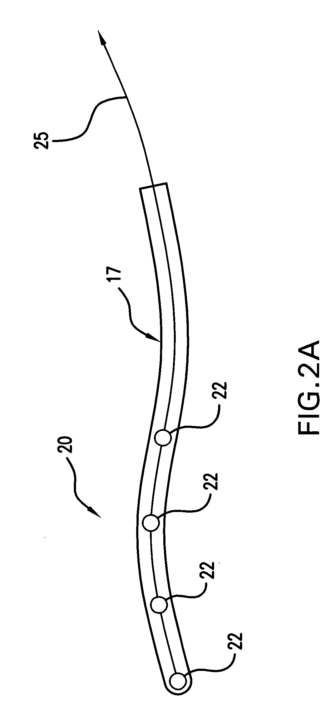
[0055] The present example demonstrates the effective measurement of local magnetic fields within the MR scanner by means of Hall sensors using a very simple Hall sensor array as shown in FIG. 3. A commercially available Hall sensor device 22 (HW-105C, sensitivity 2V / T at 15 mA Hall current, AKE, Tokyo, Japan) with a single sensitivity direction was connected to four pairwise twisted copper wires 27 (PU insulated, 100 μm), as shown in FIG. 3. The dimensions of this Hall sensor are 1.5×1×0.5 mm3. In order to reduce the induction of RF energy in the copper wires 27, small ferrite cores 29 have been mounted every 4 cm along the wire.

[0056] The Hall voltage was amplified with an ac-coupled instrumental amplifier, followed by a 16-Bit ADC (PCI-6014, National Instruments). Hall voltage was measured at different spatial positions and orientations within the MR scanner imaging space during the run of constant, bipolar magnetic field gradient pairs, as well as during a balanced steady state...

example 2

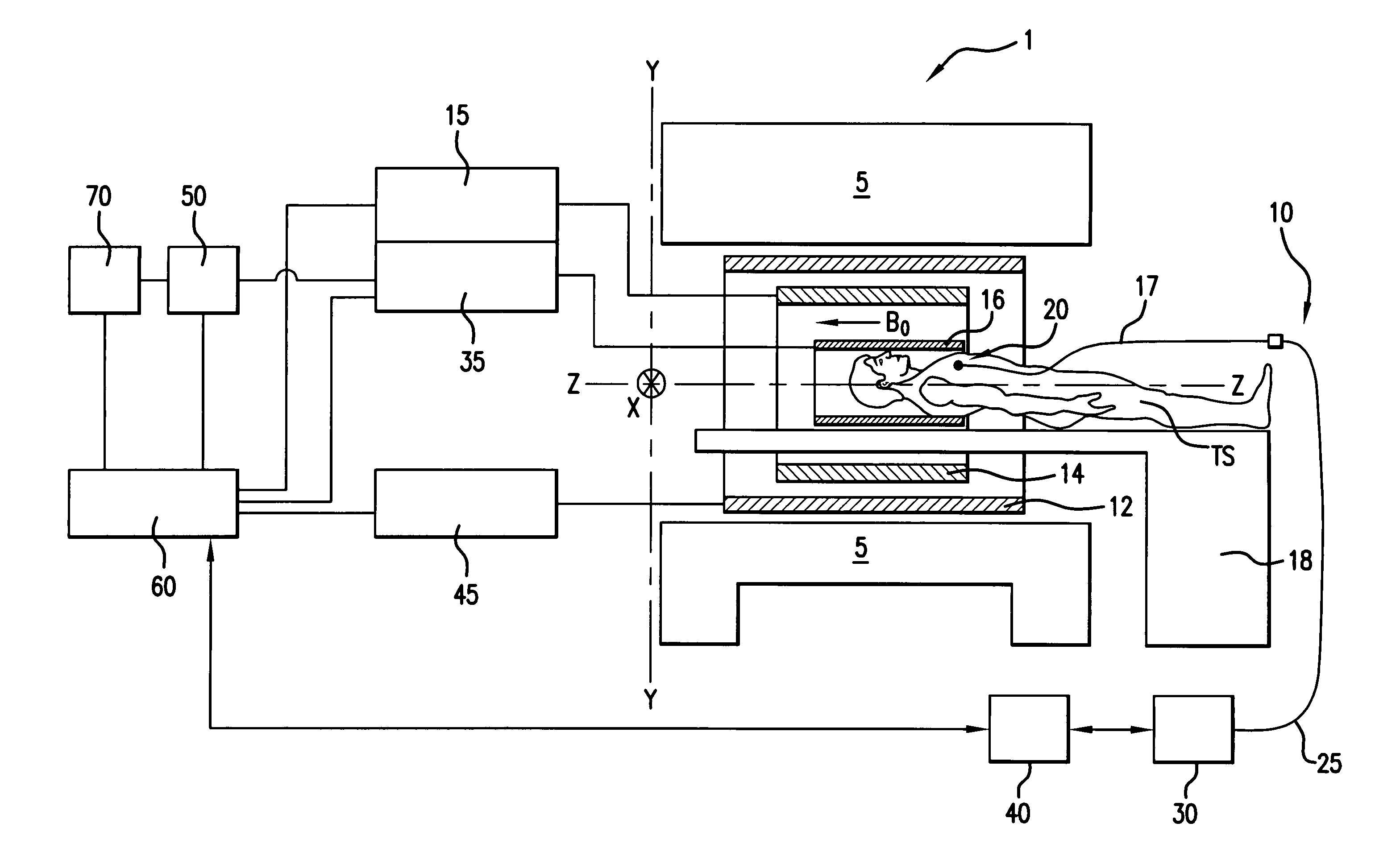
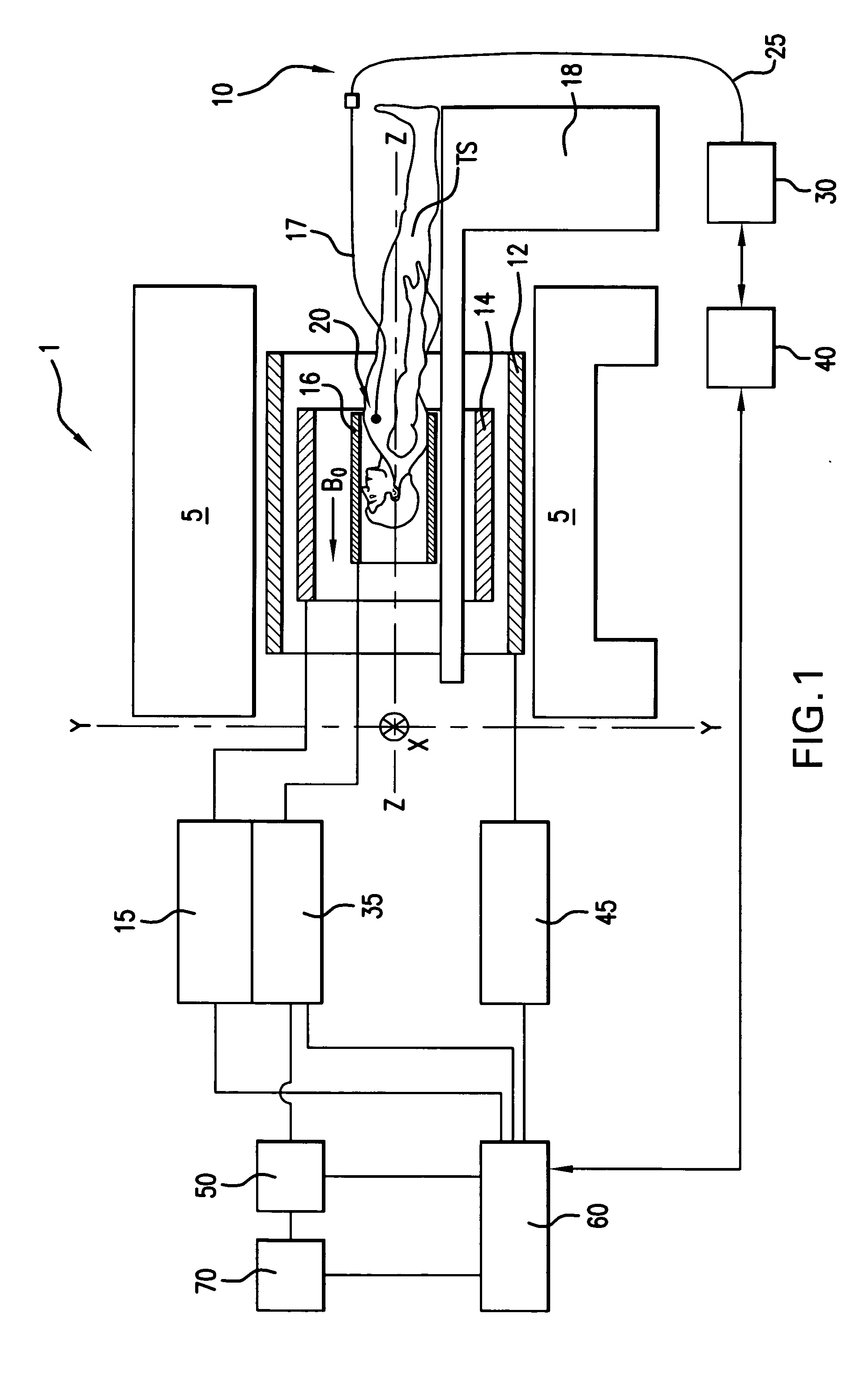
[0059] In Example 2, the Hall sensor described in Example 1 is utilized to construct a magnetic sensor navigation system in accordance with the present invention. In this illustrative embodiment, the magnetic sensor array consists of a single Hall sensor (HW-105C, sensitivity 2V / T at 15 mA Hall current, AKE, Tokyo, Japan) with a single sensitivity direction. This Hall sensor, with a single sensitivity direction, is connected to four, pairwise twisted copper wires (PU insulated, 100 μm), which are themselves electrically connected via a larger wire or connector so as to be able to send electric signals to a sensor interface. The sensor interface operates to process electronic signals received from the Hall sensor, and then sends the processed signals to a processing and control unit that operates to calculate the position of the sensor from induced Hall voltages. In addition, an ac-coupled instrumental amplifier followed by a 16-Bit ADC (PCI-6014, National Instruments) are connected ...

embodiment

Method Embodiment

[0062] Having fully and completely described various apparatus embodiments in accordance with the present invention, an illustrative method embodiment for tracking and visualizing an interventional device in an MR environment will be outlined below. More particularly, an illustrative method in accordance with the present invention is a method of guiding an interventional device in a magnetic resonance environment, which includes the steps of: (a) providing a magnetic sensor navigation system in accordance with the present invention, such as a system comprising: (i) a magnetic sensor array, including one or more magnetic non-Faradaic sensors attached to an interventional device; (ii) a sensor interface operatively connected to receive a signal from each sensor of the array, wherein the sensor interface operates to generate a processed signal from one or more signals received from each sensor of the array; and (iii) a processing and control unit connected to receive t...


PUM


Abstract

A magnetic sensor navigation system is disclosed, which includes: (a) a magnetic sensor array, including one or more magnetic non-Faradaic sensors; (b) a sensor interface operatively connected to receive a signal from each sensor of the array, wherein the sensor interface operates to generate a processed signal from one or more signals received from each sensor of the array; and (c) a processing and control unit connected to receive the processed signal, wherein the processing and control unit operates to calculate a spatial position of the sensor array using the processed signal when the sensor array is placed within a magnetic resonance environment of an MR scanner.

Description

FIELD OF THE INVENTION [0001] The present invention relates to a method and an apparatus for tracking and visualizing interventional devices during magnetic resonance imaging (MRI) scanning. More particularly, the present invention pertains to an active navigation technique and apparatus that utilizes direct measurement of local linear magnetic field gradients, which are used for image encoding in the MR environment, by using either Hall sensors or other magnetically sensitive sensing devices. In this way, the present invention provides information for tracking and visualizing an interventional device based on direct measurements of the local linear magnetic field gradients and not via the measurement of the nuclear magnetic resonance signal. BACKGROUND OF THE INVENTION [0002] As is generally known, magnetic resonance (MR) imaging has several unique attributes that can be exploited for guiding minimally invasive interventions. Among these include (a) an inherent high tissue contrast...

Claims


Application Information

Patent Timeline
Patent Type & Authority Applications(United States)
IPC IPC(8): A61B5/05A61B5/055A61B5/06
CPCA61B5/055A61B5/06G01R33/287
Inventor SCHEFFLER, KLAUS
Owner UNIVERSITY OF BASEL
Why Eureka
Try Eureka