Digital broadcast receiving device and method

Active Publication Date: 2005-11-03
MAXELL HLDG LTD
View PDF6 Cites 35 Cited by
  • Summary
  • Abstract
  • Description
  • Claims
  • Application Information

AI Technical Summary

Benefits of technology

[0008] In this way, in the case of receiving the broadcast using the hierarchical transmission in the state that the reception quality is greatly reduced, it is possible to provide good reception by changing or switching from a weak hierarchical class or “layer” to a strong layer. An approach to determining the timing for performing such switching operation is disclosed, for example, in JP-A-2000-165766 (page 5, FIG. 1), which teaches that the reception quality of an input signal is judged by detection of a with-time variation amount of the input signal characteristics at a front end unit, such as an electric field strength, carrier-to-noise (C / N) value or bit error rate (BER), followed by an attempt to switch to an optimal reception hierarchy layer. With this approach, it is possible, in the case of receiving hierarchically transmitted digital terrestrial broadcast via handheld terminals or mobile / movable bodies such as auto cars or else, to play back and display video images and audio / voice sounds with excellent reception quality.
[0013] According to this invention, in the digital broadcast receiver device, it becomes possible to achieve excellent reproduction of recorded television programs.

Problems solved by technology

Unfortunately, prior known digital broadcast receivers with built-in HDDs suffer from problems which follow.
Typically, the HDD-embedded digital broadcast receivers are such that when digital broadcast is being received by a handheld terminal or a mobile / movable body such as a land vehicle or the like, the reception quality can decrease resulting in occurrence of errors in a received stream, although digital terrestrial broadcast is designed to employ specific schemes and techniques that take account of mobile / movable-body reception, such as the OFDM (Orthogonal Frequency Division Multiplizing) technology and frequency / time interleave techniques.
This in turn causes the digital broadcast reception by means of mobile / movable bodies to experience an appreciable variation in reception quality due to any possible phasing, multi-path, or carrier-to-noise (C / N) deterioration or else.
Once the reception quality significantly deteriorates, error correction becomes impossible, resulting in errors taking place in the received stream.
However, the above-noted conventional receivers are faced with a problem which follows.
When recording a received stream to an HDD and reproducing the same, any successful playback and visual display are no longer possible because of the following fact: for example, in order to record streams of a weak hierarchical layer and of a strong layer simultaneously and then reproduce this stream, the timing for switching between hierarchical layers in the state that the reception quality during recording is extremely deteriorated is kept unknown.
This results in the hierarchy switch timing becoming unknown, which leads to the lack of an ability to perform successful playback and display operations.

Method used


Image

  • Digital broadcast receiving device and method
  • Digital broadcast receiving device and method
  • Digital broadcast receiving device and method

Examples


embodiment 1

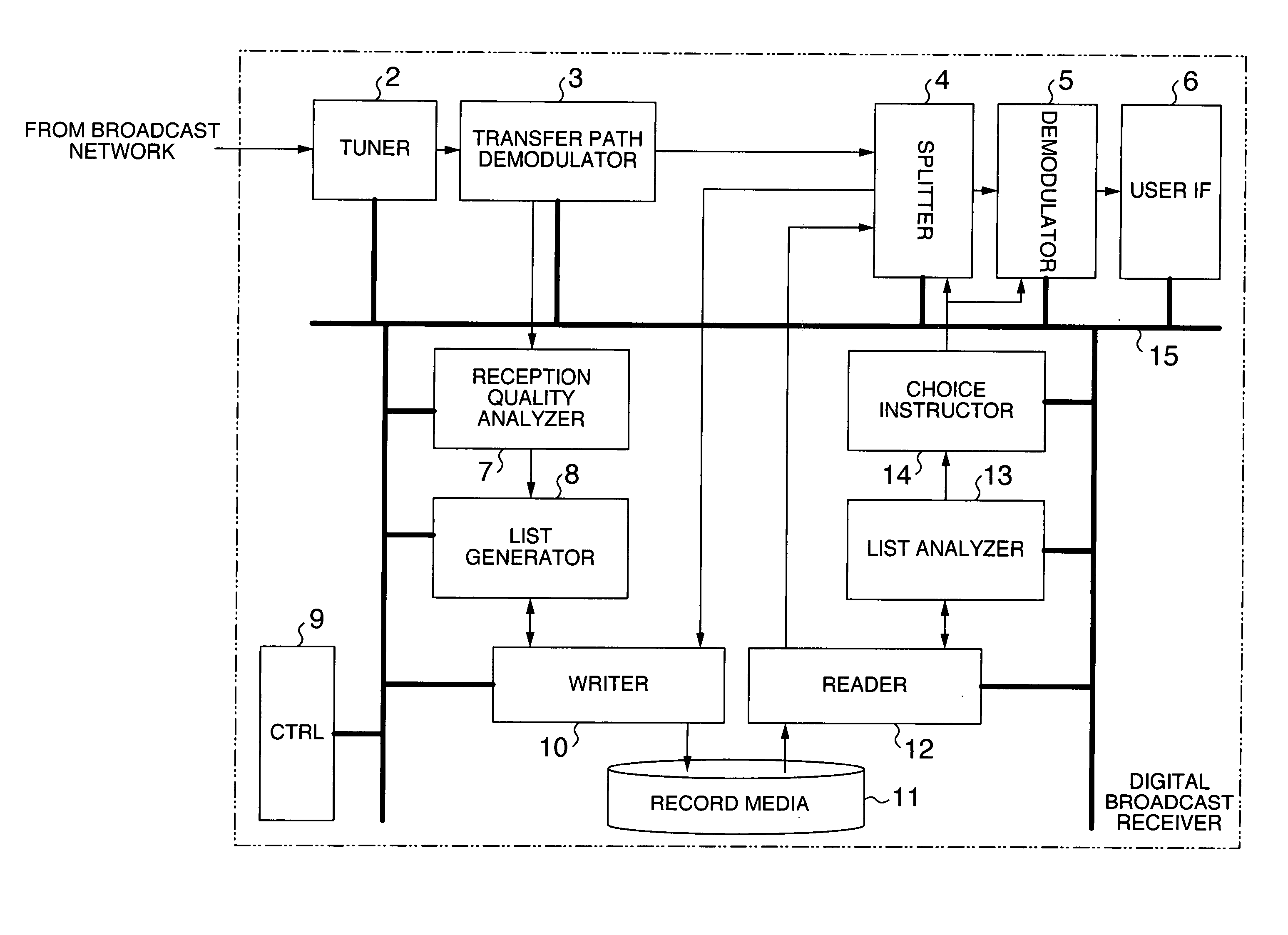
[0029]FIG. 1 is a block diagram showing an exemplary configuration of a digital broadcast receiving device having a built-in storage output device in accordance with a first embodiment of the invention is applied.

[0030] In FIG. 1, the digital broadcast receiver device 1 includes a tuner 2, a transmission path demodulation unit 3, a separation unit (for example, demultiplexer) 4, a reception quality analysis unit 7, a list generation unit 8, a writing unit 10, a recording medium (e.g., a hard disk or a memory or an optical disk) 11, a readout unit 12, a list analysis unit 13, a selection instruction unit 14, a control unit (e.g., central processing unit or “CPU”) 9, and a system bus unit 15. The digital broadcast receiver 1 also includes a demodulation unit (e.g., an MPEG decoder) 5 and a user interface unit 6 (for example, a key board or mouse or remote commander for use as an input device, a display device using a cathode ray tube (CRT) or liquid crystal display (LCD) or plasma di...

embodiment 2

[0058] Turning to FIG. 8, there is shown in block diagram form an exemplary configuration of a digital broadcast receiver device with its built-in storage / output module in accordance with a second embodiment of this invention.

[0059] The configuration of this embodiment is similar in configuration to the first embodiment shown in FIG. 1 with an insertion unit 20 and a detection unit 21 being added thereto and also with replacement of a reception quality analyzer unit 16, list generation unit 7, list analyzer unit 18 and selection instruction unit 19. The other parts or components are the same as those shown in FIG. 1 both in structure and in operation, so their explanations will be eliminated while adding the same reference numerals to the same components. An explanation below will be related only to operations of the added or replaced components—i.e., insertion unit 20, detector 21, reception quality analyzer 16, list generator 17, list analyzer 18 and selection instruction unit 19...


PUM


Abstract

This invention relates to a digital broadcast receiver device capable of performing excellent reproduction equivalent to recording sessions in the case of receiving digital broadcast by handheld terminals or mobile / movable bodies, such as land vehicles, and then recording it in a storage device for reproduction. For example, when recording hierarchically transmitted digital broadcast on a recording medium, the reception quality is analyzed by a reception quality analyzer based on the information from a transmission path demodulator. A list generator generates a reception quality list from an analysis result from the reception quality analyzer and time information from a writing unit and then records it on the record medium. Upon playback from the record medium, the reception quality list is analyzed by a list analyzer. A selection instruction unit selects the optimum hierarchical service and then performs playback and display.

Description

INCORPORATION BY REFERENCE [0001] The present application claims priority from Japanese application JP2004-123631 filed on 20 Apr., 2004, the content of which is hereby incorporated by reference into this application. BACKGROUND OF THE INVENTION [0002] The present invention relates generally to digital broadcast receiving devices capable of recording and reproducing broadcast programs. [0003] In recent years, television (TV) broadcasting is promoted to shift from analog to digital schemes in countries around the world. In Japan also, communications satellite (CS) and broadcasting satellite (BS) broadcast services relying upon digital technologies have already commenced; in addition, digital terrestrial broadcasting services have also started in selected areas. [0004] A feature of the domestic digital terrestrial broadcast in Japan is that the orthogonal frequency division multiplex (OFDM) technique is used as its transmission scheme to thereby enable achievement of not only fixed re...

Claims


Application Information

Patent Timeline
IPC IPC(8): H03D3/00H04N5/44H04N5/76H04N5/781H04N5/85H04N5/907H04N5/91H04N7/08H04N7/081H04N7/173H04N9/804H04N9/82H04N21/426H04N21/438H04N21/4425
CPCH04N5/76H04N5/781H04N5/85H04N5/907H04N9/8042H04N21/8455H04N21/41407H04N21/4334H04N21/440227H04N21/44209H04N21/4882H04N9/8205
InventorTSURUGA, SADAOSHIROSUGI, TAKATOSHI
OwnerMAXELL HLDG LTD