
Method of purifying air

Active Publication Date: 2012-01-19
TAIYO NIPPON SANSO CORP
View PDF7 Cites 17 Cited by
  • Summary
  • Abstract
  • Description
  • Claims
  • Application Information

AI Technical Summary

Benefits of technology

[0044]According to the present invention, it is possible to reduce an amount of a purge gas which is used for regenerating an adsorbent when pre-purification of feed air is performed by the TSA method in cryogenic air separation. Therefore, it is possible to increase a product yield. Furthermore, the present invention is excellent in reproducing ability of an adsorbent. Therefore, it is possible to sufficiently perform adsorption and regeneration even if air introduced in a column has not been cooled by a freon refrigerating machine or the like, and the present invention does not damage the environment.

Problems solved by technology

When air which includes said impurities is cooled to a cryogenic temperature as it is, for example, there is a possibility that water, carbon dioxide and nitrogen oxide become solidified and choke piping and the like, or that hydrocarbons concentrate in a liquid oxygen tank and become a factor which inhibits safety operations.
Air purification performed under conditions wherein a refrigerating machine is not used has a problem.
Accordingly, when a refrigerating machine is not used and air which is saturated with water is not sufficiently cooled by an after-cooler, a large amount of water enters an adsorption column.
However, it should be understood that the aforementioned yields are rough estimates, since product yield in a cryogenic air separation method depends on conditions such as operation pressure and total processes of the cryogenic air separation method.
Accordingly, as the case stands, current performances of pre-purification limit a total increase of a production performance of a cryogenic air separation method.
However, it is still necessary to use a large amount of a purge gas in pre-purification, and therefore a constant amount of a waste gas generated in a distillation step is required for pre-purification.
Accordingly, there is a problem in that a sufficient product yield which corresponds to the improved distillation performances cannot be achieved.
However, a high-performance carbon dioxide adsorbent, which has been used in recent years, has a carbon dioxide adsorbing ability which remarkably deteriorates when the adsorbent adsorbs moisture.
Accordingly, it has been believed that such a method, wherein raw air which includes water and carbon dioxide to some extent is used as a part of, or all of, a purge gas as disclosed in Japanese Unexamined Patent Application, First Publication No. 60-139311, cannot be adopted in a case wherein a high-performance carbon dioxide adsorbent is used.

Method used


Image

  • Method of purifying air
  • Method of purifying air

Examples


example 1

[0097]The method of the present invention was simulated under the conditions of adsorption columns which were similar to those of Comparative Example 1.

[0098]Conditions of an adsorption column:[0099]Diameter of columns: 1.4 m[0100]Height of a filled moisture adsorbent layer: 0.808 m[0101]Height of a filled carbon dioxide adsorbent layer: 0.655 m

[0102]Conditions of feed air: 700 kPa (A), 40° C., 5800 Nm3 / h

[0103]Calculation was performed such that an adsorption step and a regeneration step (decompressing, heating, cooling and pressurizing) were performed for two hours so that the steps were switched every two hours for each column of a two-column type pre-purification apparatus.

[0104]A purge gas was presumed a purified gas, which did not include moisture and carbon dioxide, and the same flow rate was supplied to both a heating step and a cooling step to regenerate both adsorbents.

[0105]In a heating step, a partial heating step wherein heated raw air was supplied to a moisture adsorben...

example 2

[0121]The method of the present invention was simulated under conditions of adsorption columns which were similar to those of Comparative Example 2.

[0122]Conditions of an adsorption column:[0123]Diameter of a column: 4.4 m[0124]Height of a filled moisture adsorbent layer: 0.945 m[0125]Height of a filled carbon dioxide adsorbent layer: 0.657 m

[0126]Conditions of feed air: 550 kPa (A), 40° C., 50000 Nm3 / h

[0127]An adsorption step and a regeneration step (decompressing, heating, cooling and pressurizing) were performed for two hours so that the steps were switched every two hours for each column of a two-column type pre-purification apparatus. A purge gas was presumed as a purified gas which did not include moisture and carbon dioxide, and calculation was performed such that same flow rate was supplied to a heating step and a cooling step to regenerate adsorbents.

[0128]In a heating step, a partial heating step, wherein heated raw air was introduced to a portion to which a moisture adsor...


PUM


Abstract

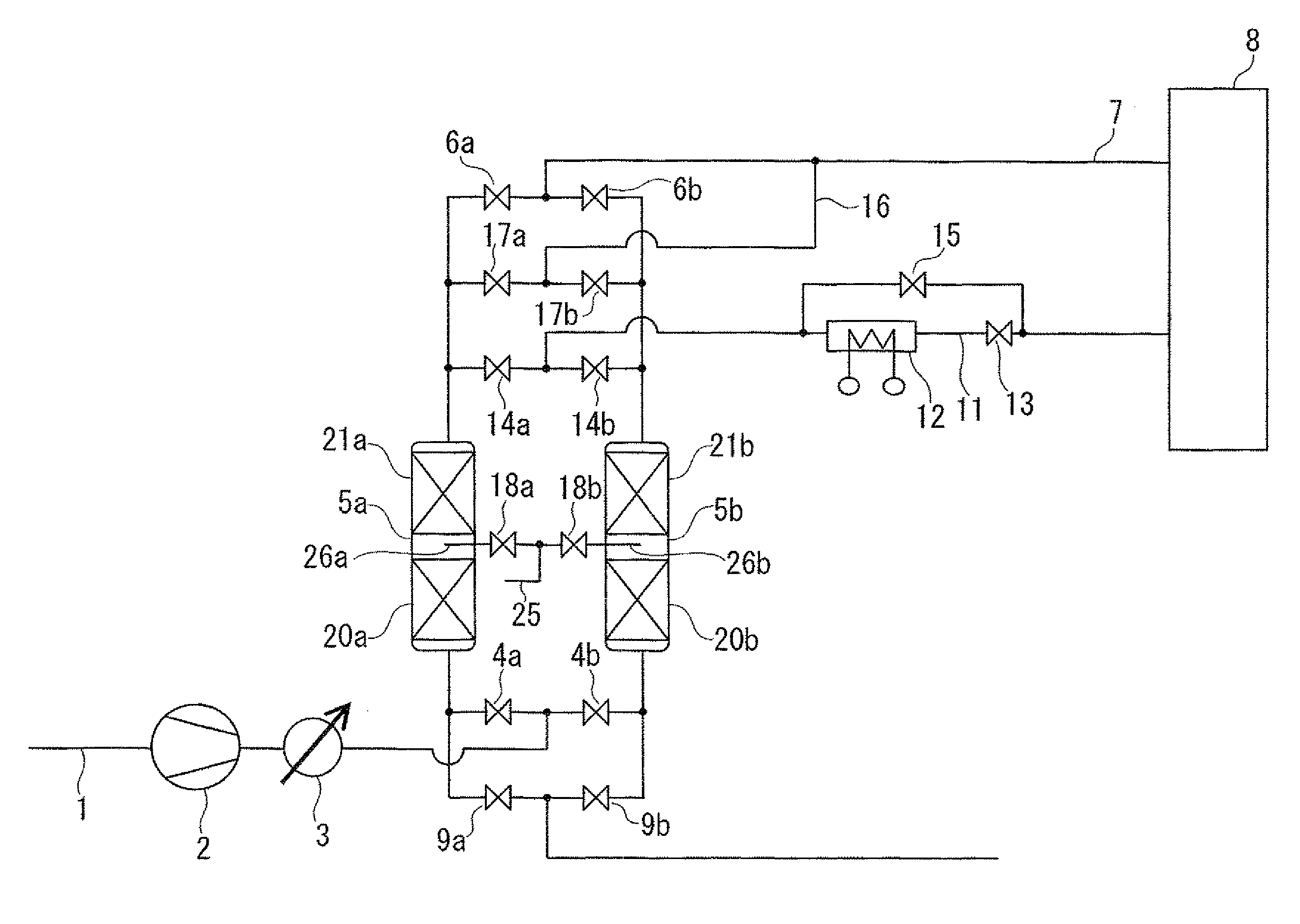
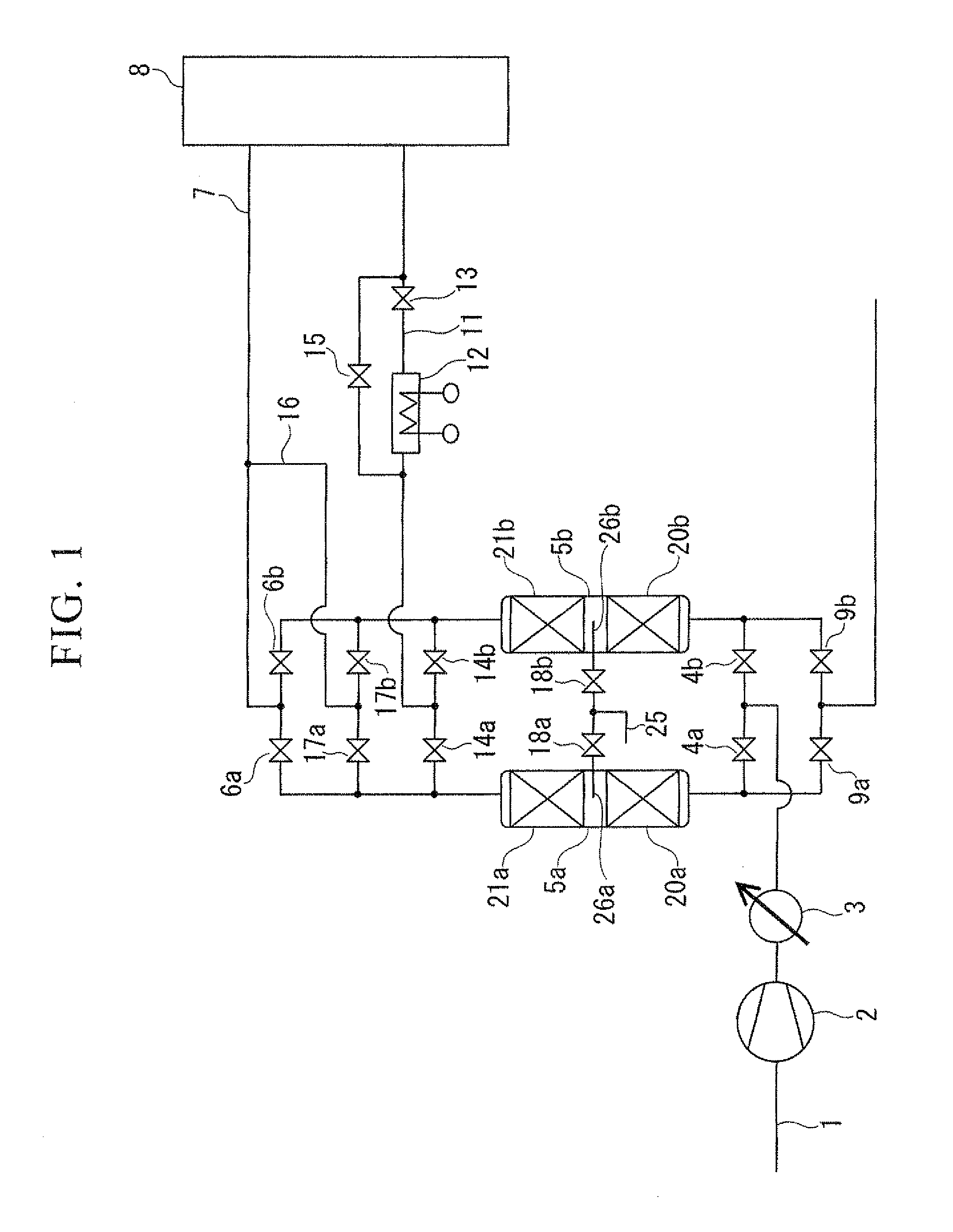
A pre-purification method of feed air for cryogenic air separation, which includes; (a) an adsorption step wherein a compressed feed air is supplied in an adsorption column, wherein a moisture adsorbent and a carbon dioxide adsorbent are filled in this order from the side where the feed air is introduced in the column, to remove water and carbon dioxide from the feed air; (b) a decompression step wherein pressure in the adsorption column is reduced; (c) a heating step wherein the adsorbents in the decompressed column are heated and regenerated, and the heating step includes a total heating step wherein the moisture adsorbent and the carbon dioxide adsorbent are heated and a partial heating step wherein the moisture adsorbent is heated; (d) a cooling step wherein the adsorbents are cooled by introducing a purge gas, which is not heated, to the adsorption column; and (e) a pressurization step wherein the cooled adsorbents are pressurized by purified air.

Description

TECHNICAL FIELD[0001]The present invention relates to a pre-purification method of feed air for cryogenic air separation.[0002]Priority is claimed on Japanese Patent Application No. 2009-058724 filed Mar. 11, 2009, the content of which is incorporated herein by reference.BACKGROUND ART[0003]In a cryogenic air separation method wherein nitrogen, oxygen, argon and the like are separated from air by distillation, it is necessary to perform a pre-step wherein water, carbon dioxide, and other trace impurities (hydrocarbons, nitrogen oxide and the like) are removed from feed air in advance before the feed air is cooled at a cryogenic temperature to perform distillation. Said pre-step is called pre-purification of air.[0004]When air which includes said impurities is cooled to a cryogenic temperature as it is, for example, there is a possibility that water, carbon dioxide and nitrogen oxide become solidified and choke piping and the like, or that hydrocarbons concentrate in a liquid oxygen ...

Claims


Application Information

Patent Timeline
IPC IPC(8): F25J3/08B01D53/02
CPCB01D53/0462B01D53/047B01D53/261B01D2257/504B01D2257/80B01D2259/40013Y02C10/08B01D2259/40028B01D2259/40043B01D2259/402B01D2259/4148F25J3/04181F25J2205/70B01D2259/4002Y02C20/40
Inventor NAKAMURA, MORIMITSUKAWAI, MASATOTAKEI, HIROYUKI
Owner TAIYO NIPPON SANSO CORP
Learn More