Method and apparatus to measure and transfer liquefied refrigerant in a refrigeration system

a technology of refrigerant and refrigeration system, which is applied in the direction of instruments, lighting and heating apparatus, heat measurement, etc., can solve the problems of low refrigerant level, temperature problem complaints, leakage of components of the system or pipes,

Inactive Publication Date: 2005-11-10
ARSHANSKY YAKOV +2
View PDF16 Cites 35 Cited by
  • Summary
  • Abstract
  • Description
  • Claims
  • Application Information

AI Technical Summary

Benefits of technology

[0016] It is to these problems that the invention is directed. An embodiment of this system will be able to measure how much refrigerant is added or removed during a service event, thus enabling close monitoring capabilities for financial and regulatory reasons. Another embodiment will further enable electronic monitoring, logging, and communication to a record-keeping system which may be on-line.

Problems solved by technology

In addition, leaks can develop in the components of the system or in pipes connecting the components from a broad range of causes.
Often, low levels of refrigerant are not easily identifiable.
For example, in a supermarket, there may be complaints about a temperature problem, such as the ice cream in its refrigerated case getting soft.
However, it does not measure the amount transferred.
Owners of equipment with charges of refrigerant greater than fifty pounds are required to repair leaks in the equipment when those leaks would result in the loss of more than a certain percentage of the refrigerant charge of the equipment over a continuous one year period.
For instance, owners of a commercial refrigeration system containing one hundred pounds of charge must repair leaks if they find that the system has lost ten pounds of charge over the past month.
Although ten pounds represents only ten percent of the system charge in this case, a leak rate of ten pounds per month would result in the release of over 100% of the charge over the year.
In a typical commercial or industrial refrigeration system there may be 2,000 or more fittings connecting system components, and a leak can occur in any of them.
Therefore, there is a great potential for leakage and enormous financial consequences.
These methods are inconvenient and prone to error and malfunction due to the mechanical strain on the scales, repeated use, or external influence which might bias the resulting calculation.
In addition, in many cases, technicians may simply estimate the amount of refrigerant based on how heavy the container “feels”, which, if inaccurate, can impact the cost of the service call and / or bias the EPA rate calculation.

Method used


Image

  • Method and apparatus to measure and transfer liquefied refrigerant in a refrigeration system
  • Method and apparatus to measure and transfer liquefied refrigerant in a refrigeration system
  • Method and apparatus to measure and transfer liquefied refrigerant in a refrigeration system

Examples


Embodiment Construction

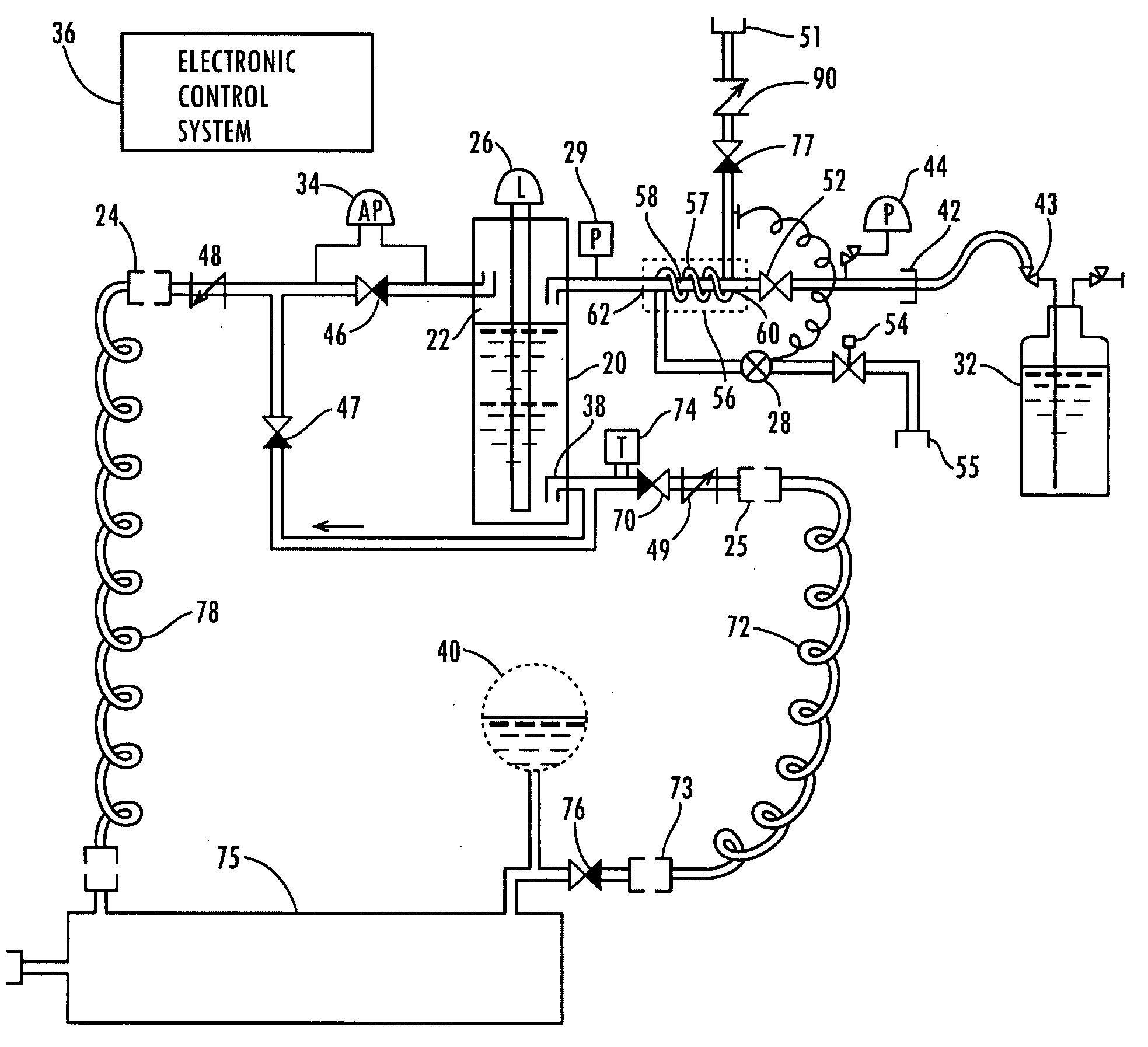
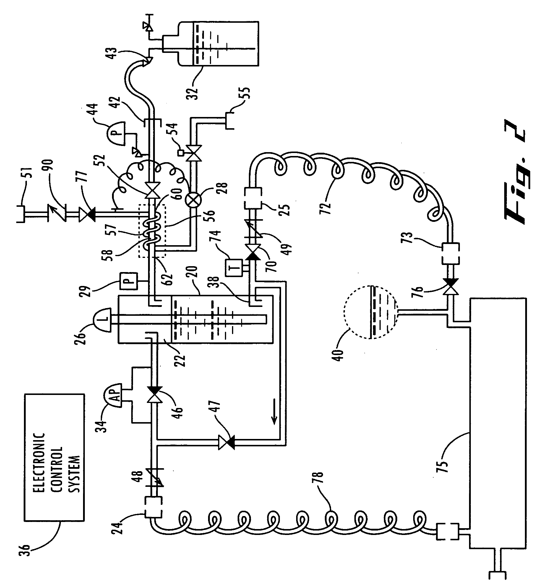
[0026] Referring now to the drawings in detail, in the preferred embodiment, FIG. 2 illustrates the apparatus 10 for measuring and transferring liquefied refrigerant to a refrigeration system 15 of the type used to refrigerate large spaces such as freezers and refrigerated cabinets in supermarkets and refrigerated warehouses, etc. As shown in FIG. 2, each switch / relay / solenoid that controls the flow of refrigerant is electromechanical and is electrically connected to an electronic control system 36. Additionally, all pressure switches, transducers, level measurement transmitters, and any other controllable element may be connected to and controlled by the electronic control system 36. Connections to the electronic control system 36 are not shown in the drawings.

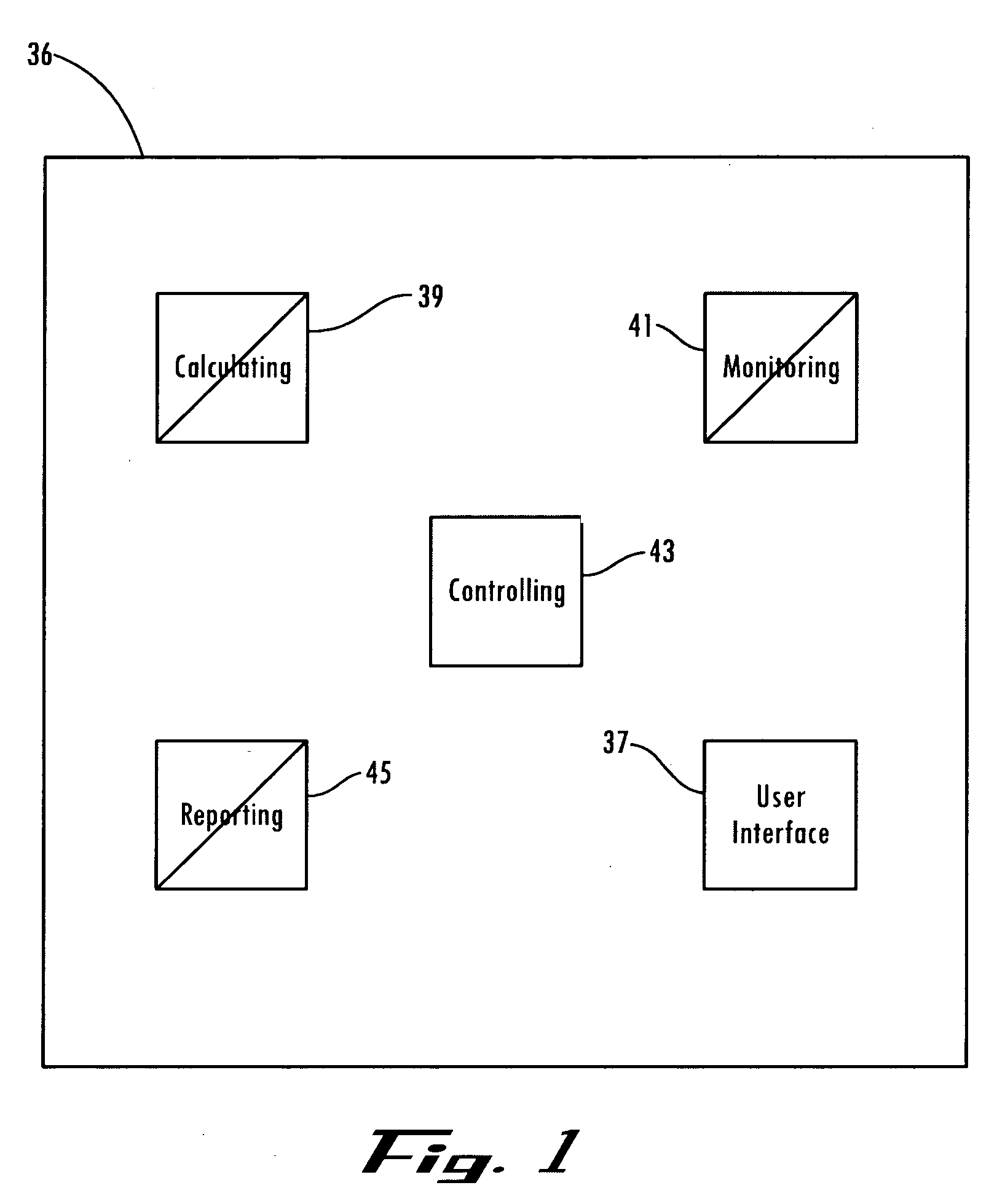
[0027] Referring to FIG. 1, the electronic control system 36 includes a processing device which may be configured to perform many functions, including interfacing 37, calculating 39, monitoring 41, controlling 43, and report...


PUM

PropertyMeasurementUnit
pressureaaaaaaaaaa
differential pressureaaaaaaaaaa
differential pressure measurementaaaaaaaaaa

Abstract

A method, system and apparatus for transferring a measured level of liquefied refrigerant to a refrigeration system includes the steps of purging a calibration container; filling the calibration container with liquefied refrigerant from a liquefied refrigerant supply to a desired level; and charging a system with the liquefied refrigerant from the calibration container.

Description

FIELD OF THE INVENTION [0001] This invention concerns the replacement of liquefied refrigerant in refrigeration systems. A measured amount of refrigerant fluid is charged into the refrigeration system. BACKGROUND OF THE INVENTION [0002] Refrigeration fluids, commonly known as refrigerants, are the media used for heat transfer in a refrigeration system to absorb heat when the fluid is at a low temperature and low pressure and to give up heat when the fluid is at a high temperature and a high pressure. This involves changes of state of the refrigerant. [0003] The common refrigerants for commercial refrigeration systems include R-22, R-404a, R-507, R-410, R-407, R-134a, among others and are widely used. Natural gas (consisting of 95% methane, such as R-50) and propane (R-290) are also typical refrigerants along with others belonging to the propane and methane series. At present time, a natural refrigerant such as carbon dioxide (R-744) is becoming popular. On the other hand, all refrig...

Claims


Application Information

Patent Timeline
Patent Type & Authority Applications(United States)
IPC IPC(8): F25B43/04F25B45/00G01K13/00
CPCF25B45/00F25B2345/001F25B2345/007F25B2345/004F25B2345/002
Inventor ARSHANSKY, YAKOVWICKBERG, PAUL THOMASJOHNSON, DANIEL THOMAS
Owner ARSHANSKY YAKOV
Why Eureka
Try Eureka