Magnetic impulse applied sleeve method of forming a wellbore casing

a wellbore casing and magnetic impulse technology, applied in the field of oil and gas exploration, can solve the problems of increased drilling rig time, increased cost of large borehole, and required equipment changes, so as to improve the sealing of wellbore casing joints, and improve the sealing of tubular members

Inactive Publication Date: 2005-11-10
ENVENTURE GLOBAL TECH LLC
View PDF99 Cites 48 Cited by
  • Summary
  • Abstract
  • Description
  • Claims
  • Application Information

AI Technical Summary

Benefits of technology

[0008] According to one aspect of the present invention, a method of forming a wellbore casing within a borehole that traverses a subterranean formation is provided that includes externally applied tubular sleeve for improved sealing a wellbore casing joints.
[0009] According to another aspect of the present invention, a method of forming a wellbore casing within a borehole that traverses a subterranean formation is provided that includes magnetic impulse method for externally applying a tubular sleeve for improved sealing of wellbore casing joints.
[0010] According to another aspect of the present invention, a method of forming a wellbore casing within a borehole that traverses a subterranean formation is provided that includes expanding joined tubular members such as joined wellbore casings with a tubular sleeve externally applied to the surfaces of the joined wellbore casing and overlapping the joint thereby maintaining an improved seal of the wellbore casing joints after expansion.
[0011] According to another aspect of the present invention, a method of improving the seal of tubular members that are connected and then expanded is provided, that includes using a magnetic impulse method for externally applying a tubular sleeve to the joint between the tubular members prior to expanding the connected tubular members.
[0012] According to another aspect of the present invention, an improved method of connecting wellbore casing tubular member is provided that includes forming raised ring portions to enhance surface contact stress in the coupling connection and subsequently applying inward radial force with a tubular sleeve imposed by magnetic impulse method for improved sealing of the joints between the tubular members.

Problems solved by technology

Such a large borehole diameter involves increased costs due to heavy casing handling equipment, large drill bits and increased volumes of drilling fluid and drill cuttings.
Moreover, increased drilling rig time is involved due to required cement pumping, cement hardening, required equipment changes due to large variations in hole diameters drilled in the course of the well, and the large volume of cuttings drilled and removed.
Existing methods for radially expanding and plastically deforming tubular members coupled to one another by threaded connections are not always reliable, and do not always produce satisfactory results.
In particular, the threaded connections can be damaged during the radial expansion process.
Furthermore, the threaded connections between adjacent tubular members, whether radially expanded or not, are typically not sufficiently coupled to permit the transmission of energy through the tubular members from the surface to the downhole location.

Method used


Image

  • Magnetic impulse applied sleeve method of forming a wellbore casing
  • Magnetic impulse applied sleeve method of forming a wellbore casing
  • Magnetic impulse applied sleeve method of forming a wellbore casing

Examples


Embodiment Construction

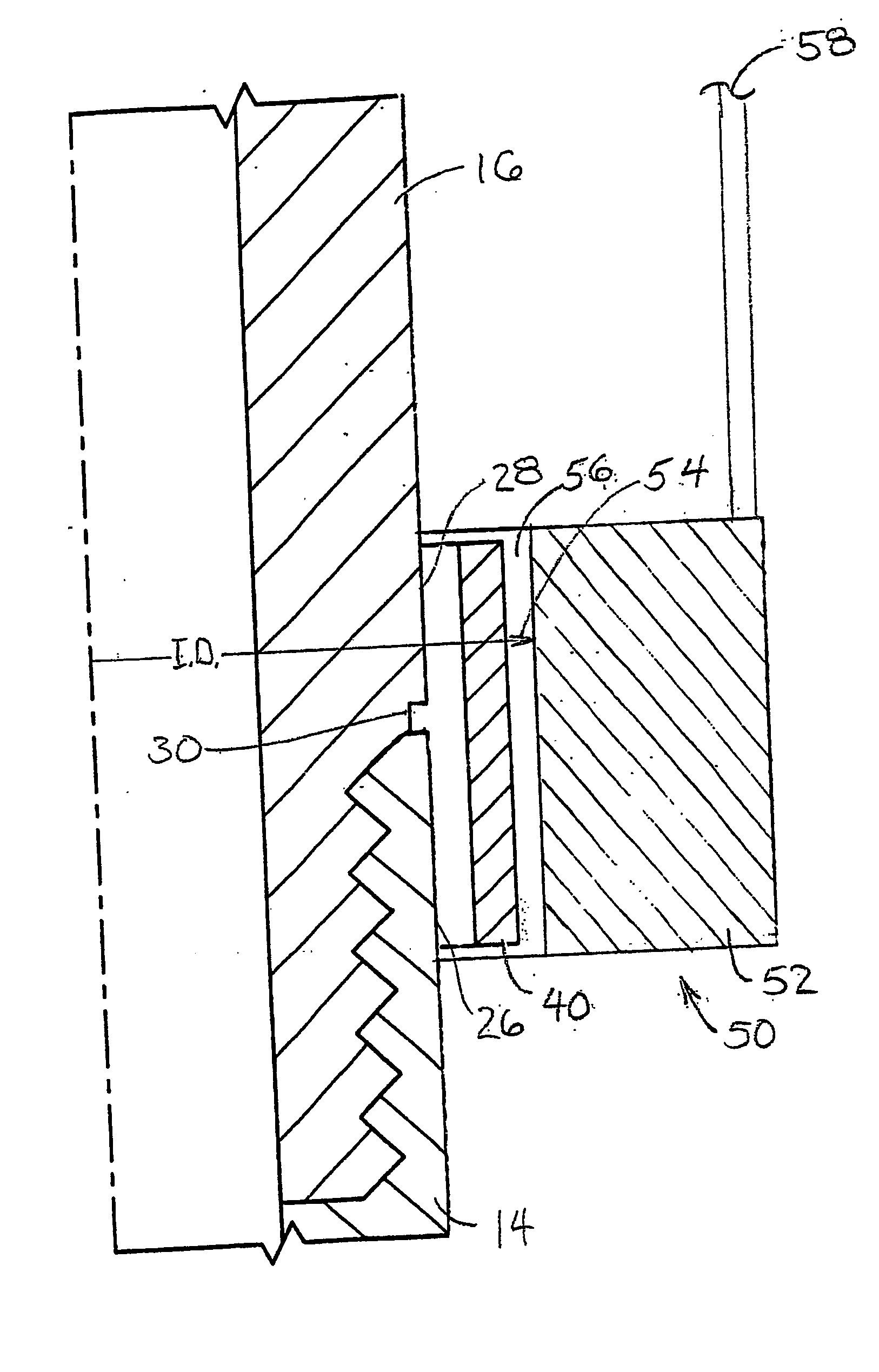
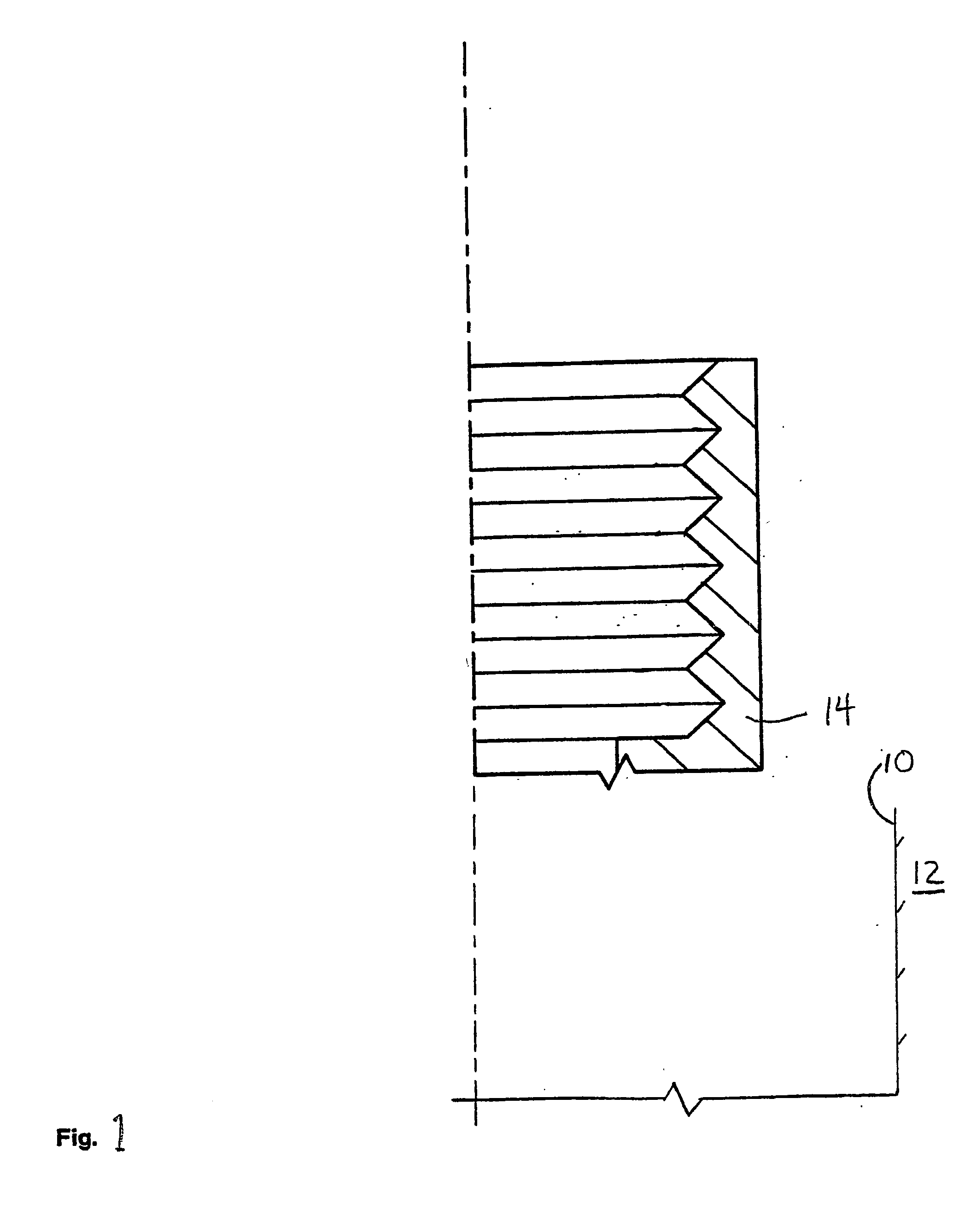
[0023] Referring to FIG. 1, a borehole 10 that traverses a subterranean formation 12 includes a first tubular member 14, such as a first wellbore casing 14 that is positioned within and coupled to the borehole. In several exemplary embodiments, tubular members in the form of wellbore casings will be described and depicted. It will be understood that although the methods, particularly advantageous for forming wellbore casings, certain advantageous features may also be applicable to other tubular members as described and claimed herein. In an illustrative embodiment, the first wellbore casing 14 may, for example, be positioned within and coupled to the borehole 10 using any number of conventional methods and apparatus, that may or may not include radial expansion and plastic deformation of the first wellbore casing 14, and / or using one or more of the methods and apparatus disclosed in one or more of the following: (1) U.S. patent application Ser. No. 09 / 454,139, attorney docket no. 25...


PUM


Abstract

A method of forming a wellbore casing within a borehole that traverses a subterranean formation includes the steps of assembling a tubular liner by coupling a threaded portion of a first tubular member to a threaded portion of a second tubular member and coupling a tubular sleeve to the threaded portions of the first and second tubular members. The method further includes positioning the wellbore casing within the borehole and radially expanding and plastically deforming the wellbore casing assembly within the borehole. The step of coupling the tubular sleeve through the threaded portions of the and second tubular members includes applying impulsive magnetic energy to the tubular sleeve.

Description

CROSS REFERENCE TO RELATED APPLICATIONS [0001] The present application is the National Stage patent application for PCT patent application Ser. No. PCT / US2003 / 025677, attorney docket number 25791.119.02, filed on Aug. 18, 2003, which claimed the benefit of the filing dates of (1) U.S. provisional patent application Ser. No. 60 / 405,610 attorney docket no 25791.119, filed on Aug. 23, 2002, the disclosures of which are incorporated herein by reference. [0002] The present application is a continuation-in-part of U.S. utility patent application Ser. No. ______, attorney docket number 25791.106.05, filed on Jan. 19, 2005, which was a continuation-in-part of U.S. utility patent application Ser. No. 10 / 511,410, attorney docket number 25791.101.05, filed on Oct. 14, 2004 which claimed the benefit of the filing date of U.S. provisional patent application Ser. No. 60 / 372,632, attorney docket number 25791.101, filed on Apr. 15, 2002, which was a continuation-in-part of U.S. utility patent appli...

Claims


Application Information

Patent Timeline
Patent Type & Authority Applications(United States)
IPC IPC(8): E21BE21B17/042E21B17/08E21B23/00E21B23/02E21B43/10F16L13/16F16L15/00F16L25/00
CPCE21B17/042E21B17/08E21B43/103F16L15/009E21B43/106F16L13/168E21B43/105
Inventor SHUSTER, MARKRING, LEV
Owner ENVENTURE GLOBAL TECH LLC
Why Eureka
Try Eureka