Eureka AIR delivers breakthrough ideas for toughest innovation challenges, trusted by R&D personnel around the world.

Phase-locked loop circuit

a phase-locked loop and loop circuit technology, applied in the direction of oscillator tubes, automatic control of pulses, angle demodulation by phase difference detection, etc., can solve the problem of two signals disengaged from the frequency, vco signal tends to drift, and eventually will no longer be considered to be in frequency-locked mode with the external reference or input signal. the effect of minimizing the probability of data loss, minimizing the unnecessary transition, and minimizing the error of detection of a frequency dis

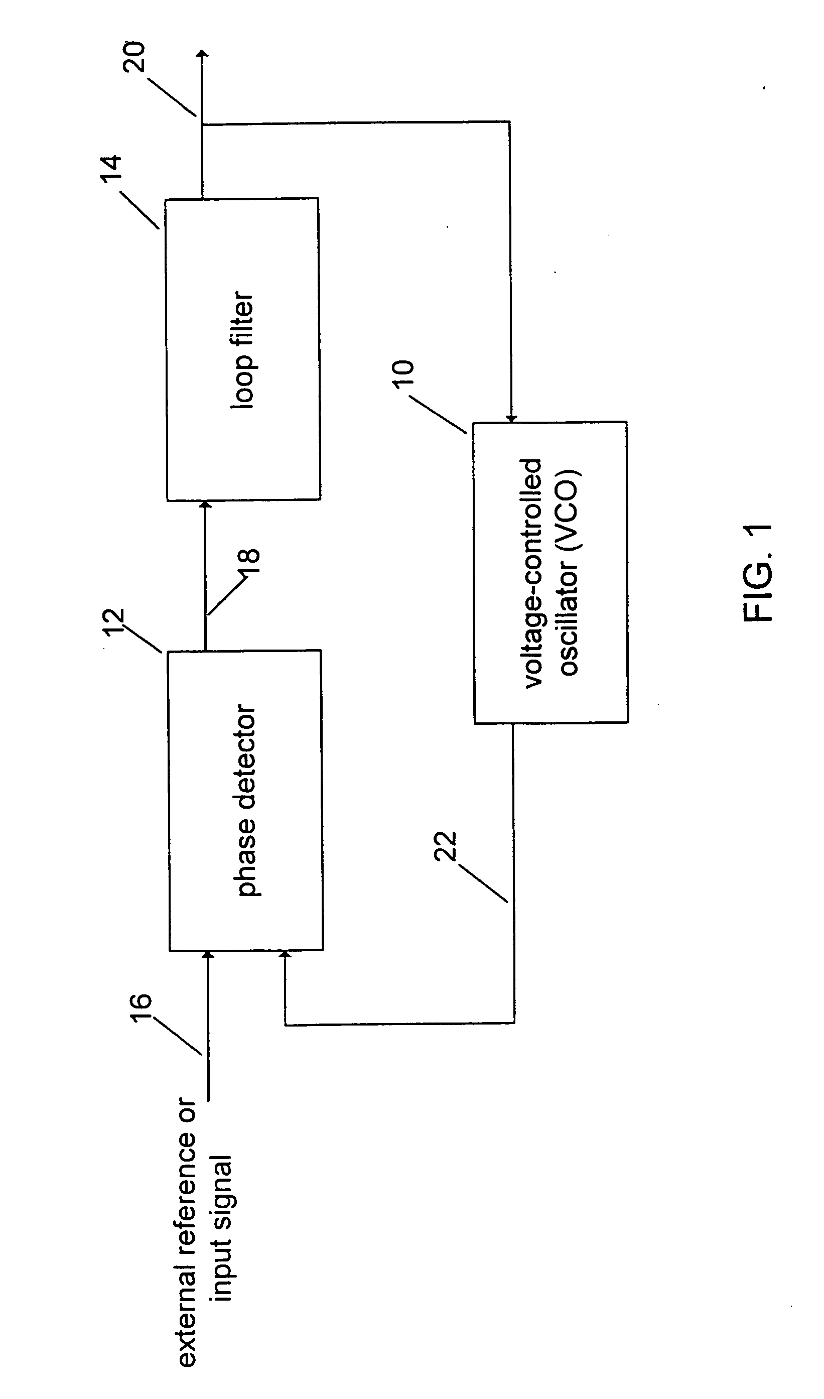
Inactive Publication Date: 2005-11-10
AVAGO TECH INT SALES PTE LTD
View PDF28 Cites 3 Cited by
  • Summary
  • Abstract
  • Description
  • Claims
  • Application Information

AI Technical Summary

Benefits of technology

[0012] The outputs of the two flip-flops are logically combined to a logic element which produces a low signal when both outputs of the flip-flops are high. In one exemplary implementation, a NAND logic function is provided to accept the output signals of the pair of flip-flops. The NAND logic function produces a low signal only when the results of both frequency differential checks are high, meaning that remedial action should be taken to rectify the frequency-locked mode. This provides the advantage that erroneous detection of a frequency discrepancy is minimized. This also provides the advantage that the PLL is given additional time to pull in the locked frequency when the PLL switches from the frequency-locked mode to the phase-locked mode.
[0013] In addition, a data present signal is logically combined with the output of the NAND logic function. An AND logic function, for example, produces a high signal only when both the data present signal and the output of the NAND logic function are high, meaning that data are present for detection and there is no frequency discrepancy. This, in turn, signifies that the phase-locked mode should be maintained. This minimizes unnecessary transition between the phase-locked mode and the frequency-locked mode thereby reducing the likelihood of data loss.

Problems solved by technology

For example, when a data signal becomes jittery or disappears entirely, the frequencies of the data signal and the VCO signal can no longer match, thereby causing the two signals to disengage from the frequency-locked mode and subsequently from the phase-locked mode.
Any unnecessary or mistaken disengagement of the frequency-locked mode thus disrupts the phase-locked mode and consequently prevents the PLL from performing its intended functions.
Moreover, very often when a PLL is engaged in a phase-locked mode and no data is available for detection, the VCO signal tends to drift and eventually will no longer be considered to be in frequency-locked mode with the external reference or input signal.
During this period when the frequency-locked mode is lost, a PLL is not capable of detecting incoming data and such data are thus lost.

Method used


Image

  • Phase-locked loop circuit
  • Phase-locked loop circuit
  • Phase-locked loop circuit

Examples


Embodiment Construction

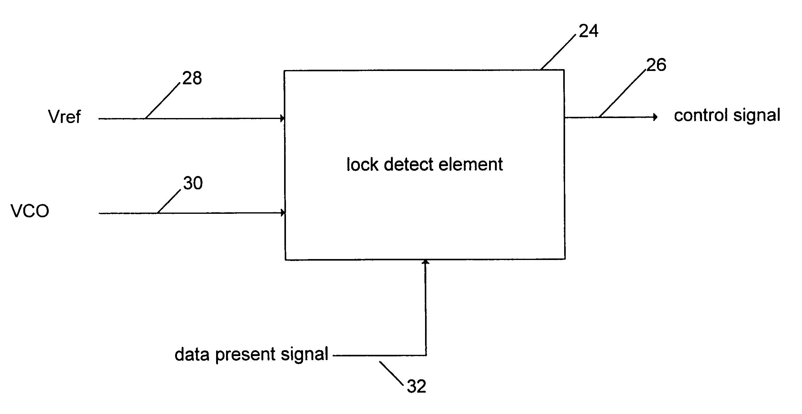
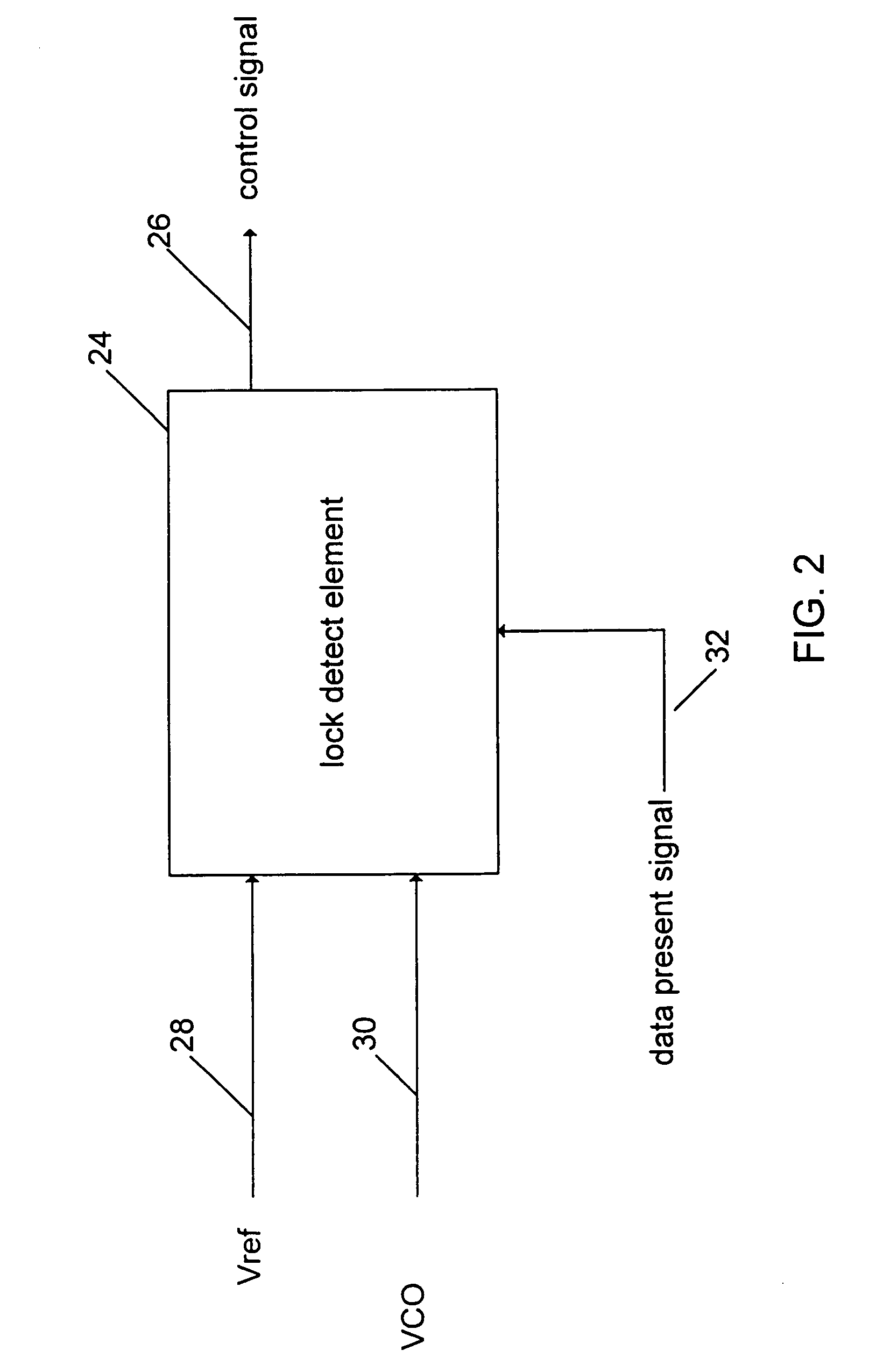
[0022] The present invention will now be described. FIG. 2 shows a simplified 10 functional block diagram of one embodiment of the present invention. The function of the lock detect element 24 is to produce a control signal 26 to indicate whether the frequency-locked mode or the phase-locked mode should be engaged.

[0023] The lock detect element 24 accepts as inputs an external reference clock 15 signal (Vref) 28 and a VCO signal 30. In circuit applications, such as in high frequency fiber optic communication networks, the VCO signal 30 may be in the gigahertz range. In such applications, it is preferable to divide down the frequency of the VCO signal 30 by a certain predetermined factor, for example, 32 or 16, so as to make frequency matching with Vref 28 more manageable. The frequencies of Vref 28 and the VCO signal 30 are designated respectively as fref and fvco.

[0024] The lock detect element 24 then compares fref and fvco to determine if the frequency differential between them ...


PUM


Abstract

Method and circuitry for improving the accuracy and efficiency of a phase-locked loop. More specifically, the present invention relates to a method and device for monitoring the frequency discrepancy between two signals in conjunction with at least one data signal so as to improve the accuracy and efficiency of a phase-locked loop. In one embodiment of the present invention, two counters are used to check the frequency differential between a VCO signal and an external reference or input signal. An adjustable threshold is provided to determine whether the frequencies of the two signals are considered to be in a frequency-locked mode. A pair of flip-flops is used to minimize any erroneous detection of frequency discrepancy by validating two consecutive results of the frequency differential check. In addition, a data present signal is used to control the transition between the phase-locked mode and the frequency-locked mode to minimize the potential data loss.

Description

CROSS-REFERENCE TO RELATED APPLICATION(S) [0001] This application is a continuation of U.S. patent application Ser. No. 10 / 843,181, filed May 11, 2004 which is a continuation of U.S. Pat. No. 6,760,394 issued on Jul. 6, 2004, which claims the benefit of priority under 35 U.S.C. § 119 from U.S. Provisional Patent Application Ser. No. 60 / 148,415 filed on Aug. 11, 1999, the disclosure of which is hereby incorporated by reference in its entirety for all purposes.BACKGROUND OF THE INVENTION [0002] The present invention relates to improving the accuracy and efficiency of a phase-locked loop. More specifically, the present invention relates to a method and device for monitoring the frequency discrepancy between two signals in conjunction with at least one data signal so as to improve the accuracy and efficiency of a phase-locked loop. [0003] A phase-locked loop (PLL) is a circuit that is capable of synchronizing an output signal generated by an oscillator with a reference or input signal i...

Claims


Application Information

Patent Timeline
Patent Type & Authority Applications(United States)
IPC IPC(8): H03L7/00H03L7/095H03L7/10
CPCH03L7/095Y10S331/02H03L7/10H03L7/113
Inventor CAO, JUNMOMTAZ, AFSHIN
Owner AVAGO TECH INT SALES PTE LTD
Why Eureka
Eureka Blog
Learn More