Phase-locked loop circuit
- Summary
- Abstract
- Description
- Claims
- Application Information
AI Technical Summary
Benefits of technology
Problems solved by technology
Method used
Image
Examples
Embodiment Construction
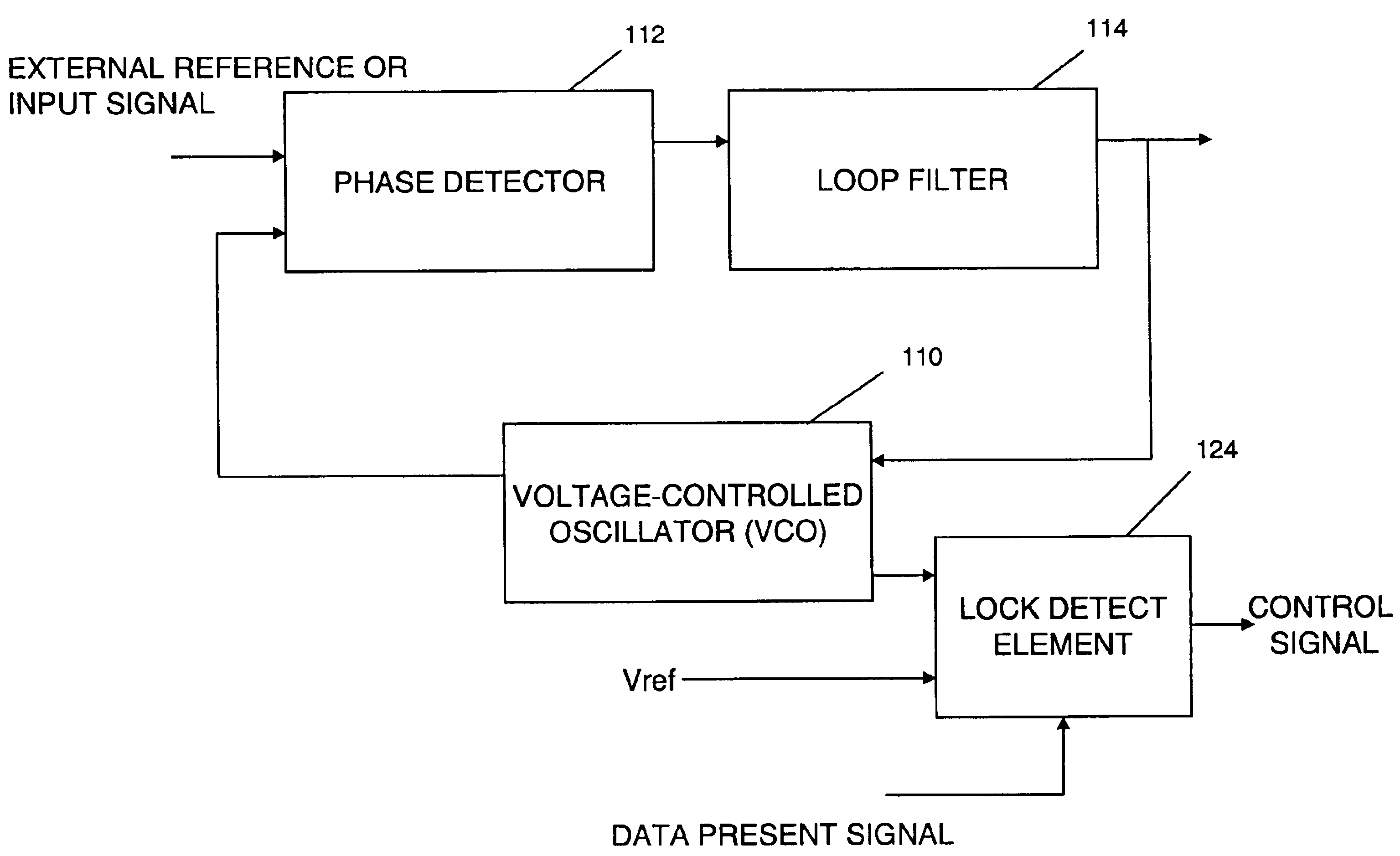
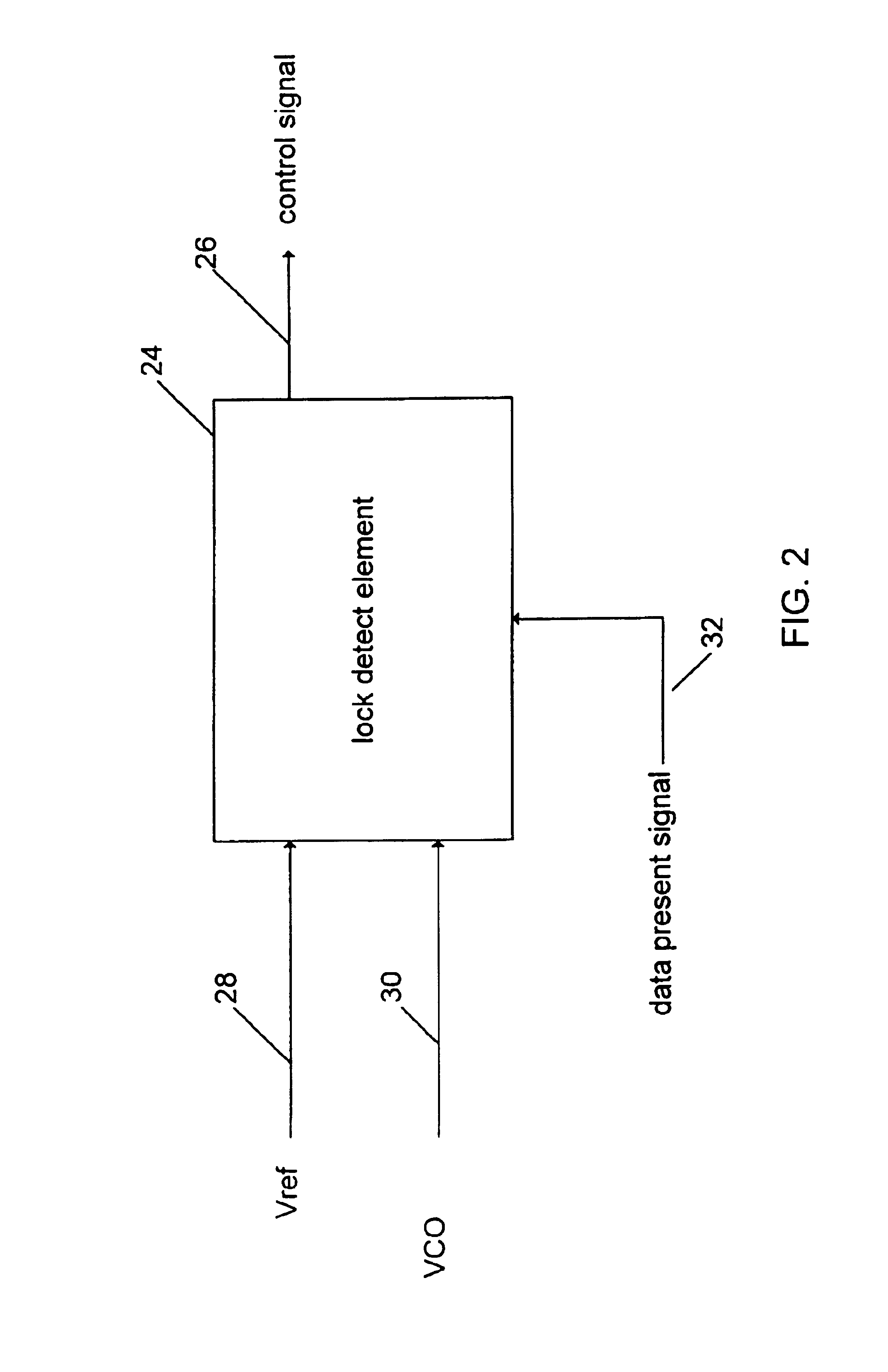
[0022]The present invention will now be described. FIG. 2 shows a simplified 10 functional block diagram of one embodiment of the present invention. The function of the lock detect element 24 is to produce a control signal 26 to indicate whether the frequency-locked mode or the phase-locked mode should be engaged.
[0023]The lock detect element 24 accepts as inputs an external reference clock 15 signal (Vref) 28 and a VCO signal 30. In circuit applications, such as in high frequency fiber optic communication networks, the VCO signal 30 may be in the gigahertz range. In such applications, it is preferable to divide down the frequency of the VCO signal 30 by a certain predetermined factor, for example, 32 or 16, so as to make frequency matching with Vref 28 more manageable. The frequencies of Vref 28 and the VCO signal 30 are designated respectively as fref and fvco.
[0024]The lock detect element 24 then compares fref and fvco to determine if the frequency differential between them is wi...
PUM
 Abstract
Description
Claims
Application Information
 - R&D
- Intellectual Property
- Life Sciences
- Materials
- Tech Scout
- Unparalleled Data Quality
- Higher Quality Content
- 60% Fewer Hallucinations
Browse by: Latest US Patents, China's latest patents, Technical Efficacy Thesaurus, Application Domain, Technology Topic, Popular Technical Reports.
© 2025 PatSnap. All rights reserved.Legal|Privacy policy|Modern Slavery Act Transparency Statement|Sitemap|About US| Contact US: help@patsnap.com


