Tiled flat panel lighting system

a flat panel lighting and lighting system technology, applied in the field can solve the problems of affecting the use of flat panel light sources, and limiting the economic production so as to facilitate the assembly of large flat panel lights

Active Publication Date: 2005-11-10
GLOBAL OLED TECH
View PDF12 Cites 183 Cited by
  • Summary
  • Abstract
  • Description
  • Claims
  • Application Information

AI Technical Summary

Benefits of technology

This patent describes a system of flat panels that can be connected together to create larger or more complex patterns. These panels are designed to work easily with different sized spaces and don't require extra expenses for every shape. Additionally, this system makes it easy to replace malfunctioning parts and adjust their configuration. Overall, this innovation offers an efficient way to design customizable and flexible lighting solutions.

Problems solved by technology

The technical problem addressed in this patent is the limitations of current manufacturing technologies used for producing large flat panel light sources with various shapes and sizes. Additionally, there is a lack of suitable flexible barrier and substrate materials needed for easy production of lamps that can conform to different shapes. Furthermore, there is no widely acceptable way to connect these flat panel light sources to external power sources.

Method used


Image

  • Tiled flat panel lighting system
  • Tiled flat panel lighting system
  • Tiled flat panel lighting system

Examples


Embodiment Construction

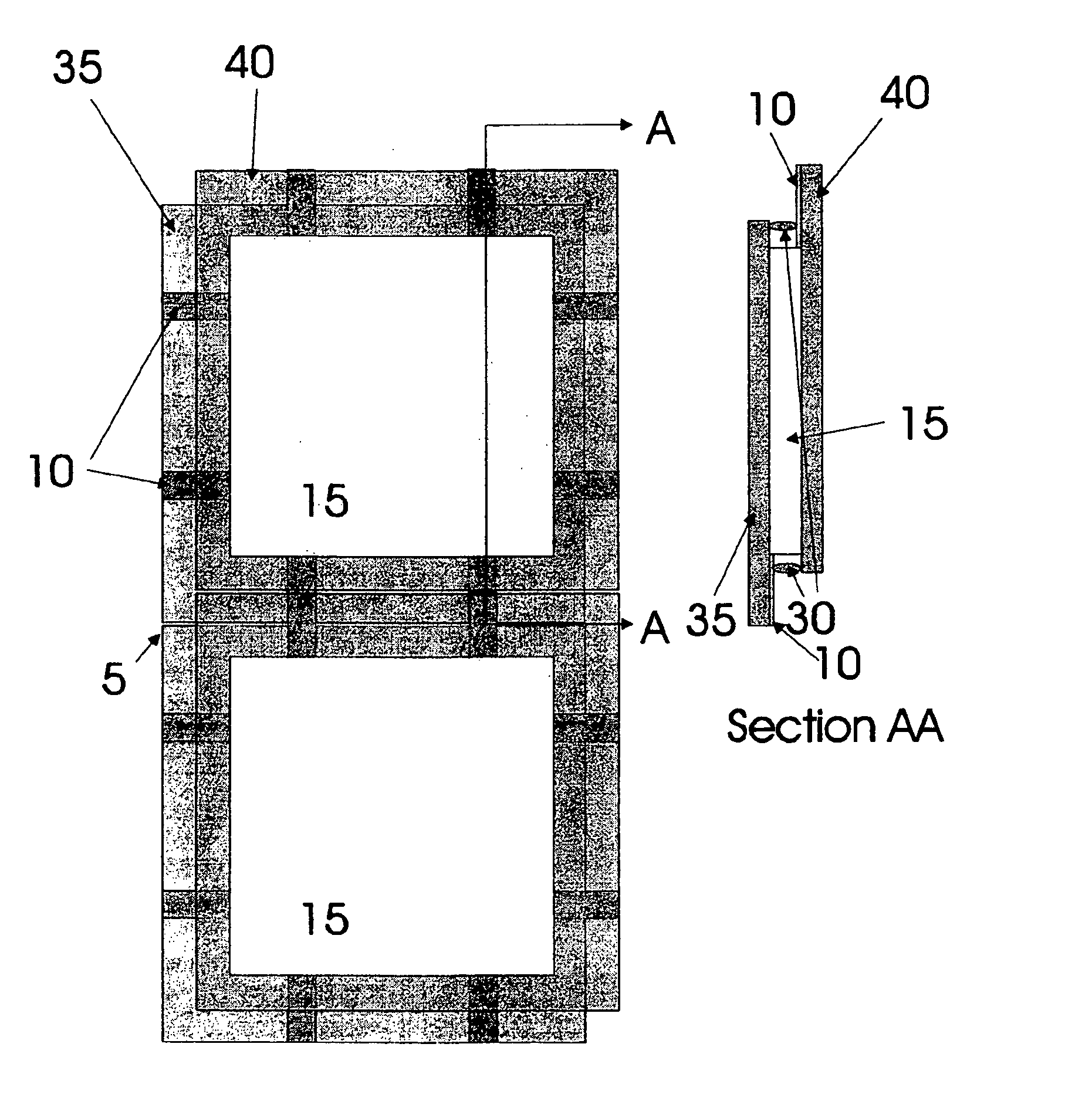
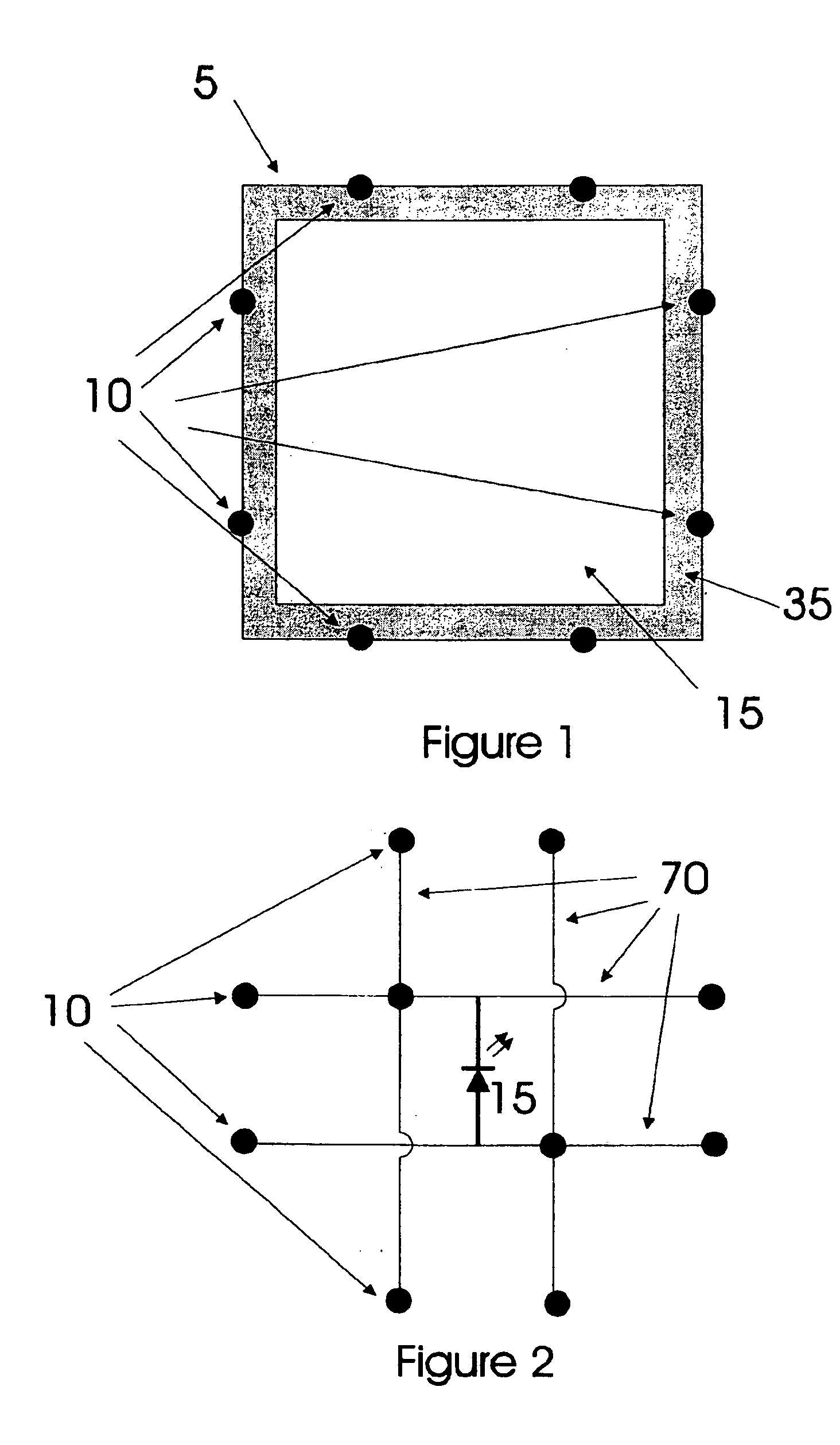
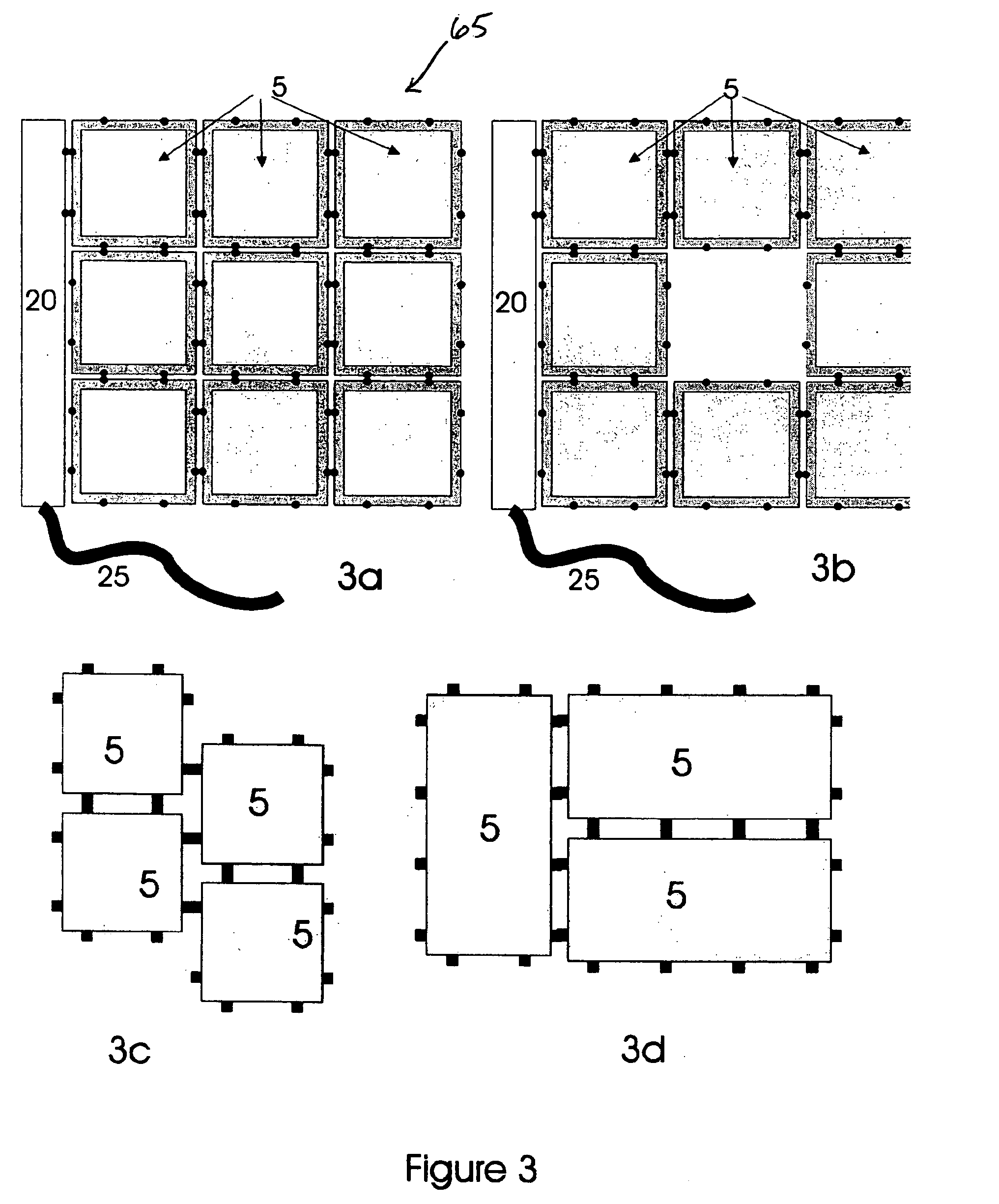
[0024] Referring to FIG. 1, a single tile 5 of a tiled flat panel lighting system is comprised of a substrate 35 upon which a set of contacts 10 and a light emitting region 15 are produced. Although drawn diagrammatically in this figure, it will be well-understood by those skilled in the art that the contacts may take a variety of forms. For example, if the light emitting region is an OLED, the contacts may, be exposed regions of the anode and cathode of the OLED device. Alternatively, the contacts may be spring metal which is connected electrically to the light emitting region. Although the tile is shown as a square, the tile may be rectangular, triangular, hexagonal, or any other shape. Further, the contacts may be present on only a subset of the edges, although there must be at least two sets of contacts on the tile. Multiple sets of contacts may be present on an edge to allow a larger tile to be connected to multiple smaller tiles. The light emitting region may contain multiple ...


PUM


Abstract

A tiled flat panel lighting system includes flat panel light emitting units, each unit comprising a light emitting region and at least two pairs of first and second electrical contacts which are accessible external to the unit, wherein the first electrical contacts of the pairs are electrically connected within the unit, the second electrical contacts of the pairs are electrically connected within the unit, the light emitting region is electrically connected to the connected first contacts and to the connected second contacts. A plurality of units may be electrically interconnected through pairs of the externally accessible first and second electrical contacts positioned at one or more adjacent edges of each of the units. In a further embodiment, a tiled flat panel lighting system comprising a plurality of flat panel light emitting units, wherein at least two of the flat panel light emitting units contain controllers, where the plurality of units are interconnected through contacts positioned at one or more adjacent edges of each of the units, wherein the interconnections provide for communications signals between the controllers.

Description


Claims


Application Information

Patent Timeline
Owner GLOBAL OLED TECH
Why Eureka
Try Eureka