
Method and apparatus for image forming capable of effectively transporting toner

a technology of image forming and toner, applied in the field of image forming methods and apparatuses, can solve the problems of toner spilling, interference of toner transporting members, and protruding portion of the first toner transporting member with the second pipe or the second toner transporting member,

Active Publication Date: 2005-11-10
RICOH KK
View PDF18 Cites 15 Cited by
  • Summary
  • Abstract
  • Description
  • Claims
  • Application Information

AI Technical Summary

Benefits of technology

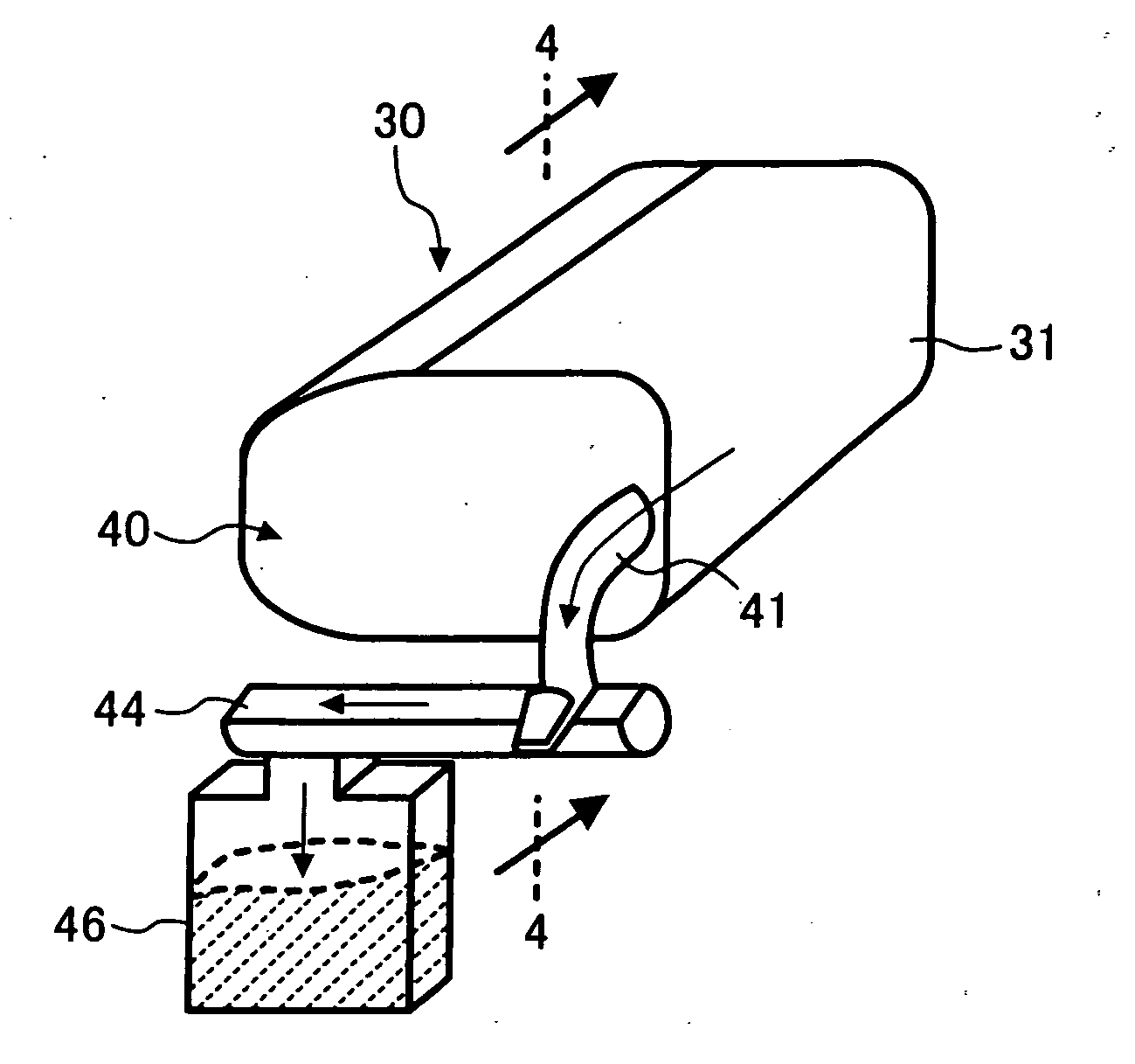
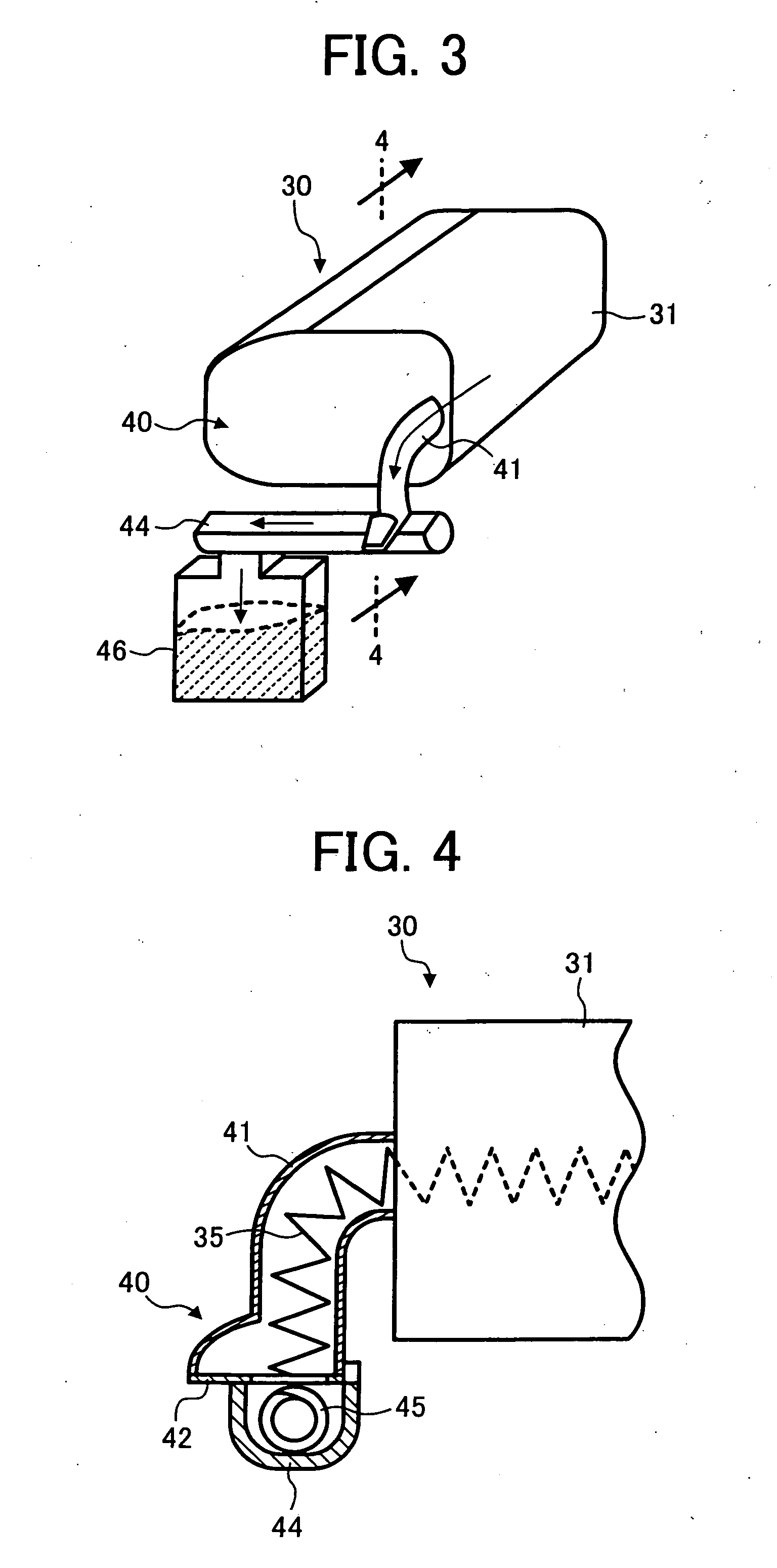
[0029] This patent specification further describes an image forming method for effectively transporting toner. In one example, an image forming method for effectively transporting toner includes: providing a photoconductor, a cleaning device, and a toner transporting device; providing, in the toner transporting device, a first toner transport path forming member, a first toner transporting member configured to expand and contract in a length direction thereof, and a length control member configured to be pressed against the first toner transporting member to keep a constant length of the first toner transporting member; inserting a part of the first toner transporting member in the first toner transport path forming member; locating the length control member at a downstream end of the first toner transport path forming member; forming a toner image on the photoconductor; causing the cleaning device to remove toner remaining on the photoconductor after a transfer of the toner image; and causing the first toner transporting member to transport the toner removed by the cleaning device through the first toner transport path forming member.
[0035] The image forming method may further include: providing, in the toner transporting device, a second toner transport path forming member and a second toner transporting member; inserting the second toner transporting member in the second toner transport path forming member; connecting the second toner transport path forming member to the first toner transport path forming member; placing the length control member at a connection point between the first and second toner transport path forming members; and causing the second toner transporting member to continue to transport, through the second toner transport path forming member, the toner transported through the first toner transport path forming member by the first toner transporting member.
[0073] The toner transporting method may further include: providing a second toner transport path forming member and a second toner transporting member; inserting the second toner transporting member in the second toner transport path forming member; connecting the second toner transport path forming member to the first toner transport path forming member; placing the length control member at a connection point between the first and second toner transport path forming members; and causing the second toner transporting member to continue to transport, through the second toner transport path forming member, the toner transported through the first toner transport path forming member by the first toner transporting member.

Problems solved by technology

As a result, a downstream end of the spiral-shaped toner transporting member may not reach an exit of the pipe or may stick out of the exit by a substantial length.
On the other hand, if the downstream end of the first toner transporting member sticks out of the exit of the first pipe, the protruding portion of the first toner transporting member may interfere with the second pipe or the second toner transporting member.
For example, the first toner transporting member may cause problems in a process of assembling the toner transporting device at a manufacturing site.
Further, if such components as the waste toner tank and a shutter are provided at the exit of the first pipe, the protruding portion of the first toner transporting member may interfere with them.
Further, the toner blocks may cause spilling of the toner when the process cartridge including the toner transporting device is detached from the image forming apparatus, for example.
It is difficult, however, to completely scrape off the toner adhered to the inner circumferential surface of the first pipe, even with the use of the stirring member.
In this case, however, the protruding portion of the first toner transporting member interferes with such components as the second pipe and the second toner transporting member, causing problems in assembling the toner transporting device, as described above.
Therefore, spilling of the toner may also occur when the process cartridge is detached from the image forming apparatus.
This type of image forming apparatus, however, needs a shutter member, increasing the number of components forming the image forming apparatus.
Further, it is possible that a relatively large amount of the toner spilled on the shutter leaks out of the toner transporting device when the process cartridge is attached to or detached from the image forming apparatus.

Method used


Image

  • Method and apparatus for image forming capable of effectively transporting toner
  • Method and apparatus for image forming capable of effectively transporting toner
  • Method and apparatus for image forming capable of effectively transporting toner

Examples


Embodiment Construction

[0104] In describing the embodiments illustrated in the drawings, specific terminology is employed for the purpose of clarity. However, the disclosure of this patent specification is not intended to be limited to the specific terminology so used, and it is to be understood that substitutions for each specific element can include any technical equivalents that operate in a similar manner.

[0105] Referring now to the drawings, wherein like reference numerals designate identical or corresponding parts throughout the several views, particularly to FIG. 1, an image forming apparatus according to an embodiment of the present invention is described.

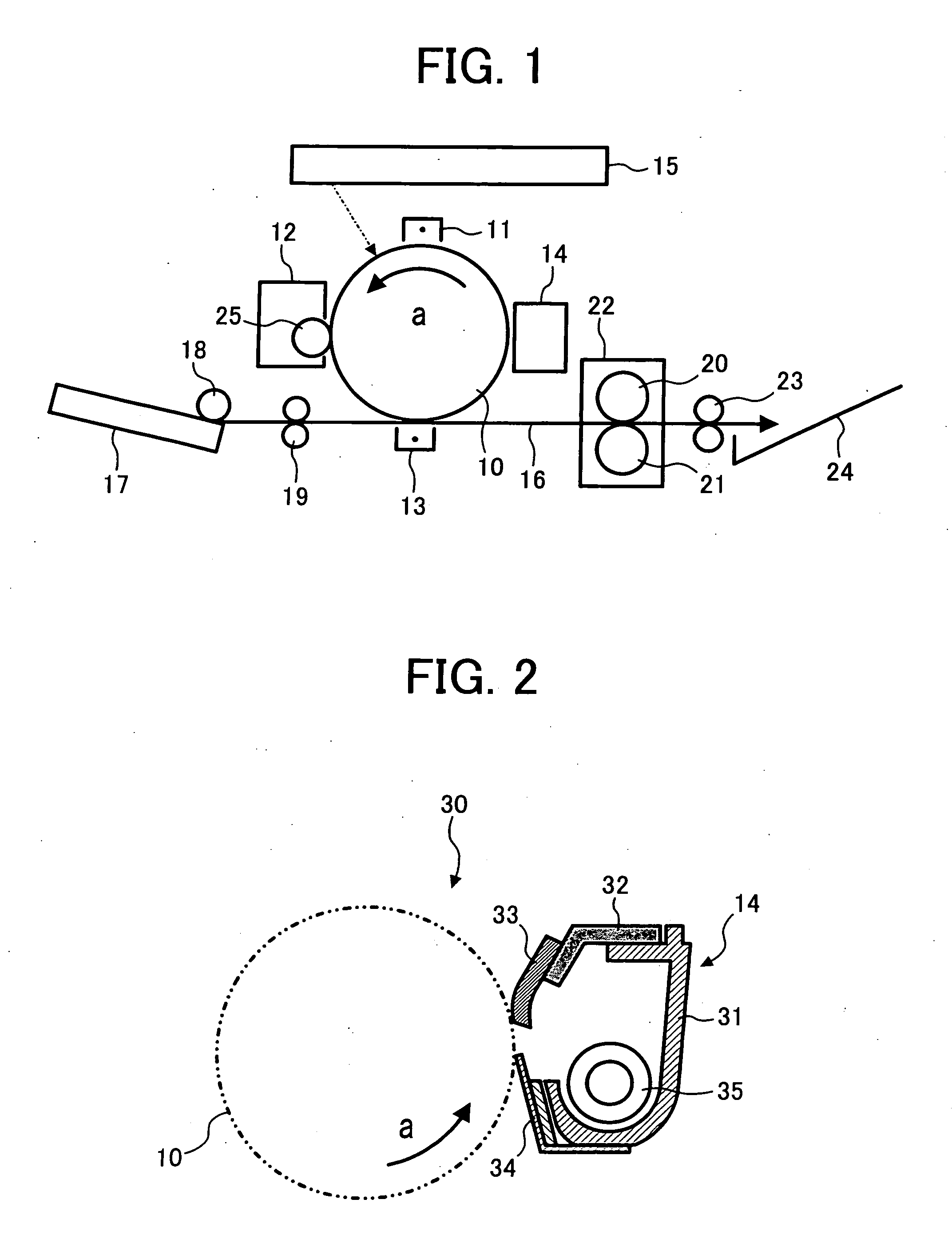
[0106] The image forming apparatus illustrated in FIG. 1 includes a photoconductor 10, a charging device 11, a developing device 12, a transferring device 13, a cleaning device 14, a writing device 15, a recording medium transport path 16, a recording medium storing cassette 17, a sheet-feeding roller 18, a registration roller pair 19, a heat r...


PUM


Abstract

An image forming apparatus includes a photoconductor, a cleaning device, and a toner transporting device. The photoconductor has a toner image formed thereon. The cleaning device removes toner remaining on the photoconductor. The toner transporting device transports the toner removed by the cleaning device. The toner transporting device includes a first toner transport path forming member, a first toner transporting member, and a length control member. The first toner transporting member is partly provided in the first toner transport path forming member, expands and contracts in a length direction thereof, and transports the toner through the first toner transport path forming member. The length control member is provided at a downstream end of the first toner transport path forming member, and is pressed against the first toner transporting member to keep a constant length of the first toner transporting member. An image forming method is also described.

Description

CROSS REFERENCE TO RELATED APPLICATIONS [0001] This application claims priority to Japanese patent application nos. 2004-139454 filed on May 10, 2004, 2005-038901 filed on Feb. 16, 2005, and 2005-057615 filed on Mar. 2, 2004, the entire contents of each of which are hereby incorporated by reference herein. BACKGROUND OF THE INVENTION [0002] 1. Field of the Invention [0003] This patent specification relates to an image forming method and apparatus, such as a copier, a printer, a facsimile machine, and a complex machine incorporating functions of a copier, a printer, a facsimile machine, and the like. More particularly, this patent specification relates to a method and apparatus for electrophotographic image forming capable of performing direct transfer or indirect transfer, which uses an intermediate transfer member to form an image on a recording medium sheet, such as a plain paper sheet and an OHP (overhead projector) film. Further, this patent specification relates to a toner tran...

Claims


Application Information

Patent Timeline
Patent Type & Authority Applications(United States)
IPC IPC(8): G03G21/00G03G21/10
CPCG03G2221/0005G03G21/105G03G2221/1624
Inventor SUDA, TAKEOKAWAHARA, SHINICHIYOSHIDA, KEIICHIHATTORI, YOSHIOTAKAHASHI, YUTAKA
Owner RICOH KK
Learn More