
Capsule type endoscope

a technology of endoscope and capsule, which is applied in the field of capsule endoscope, can solve the problems of large burden on patient and operator, large equipment, and difficult adoption of conventional endoscope in a first screening such as mass screening

Inactive Publication Date: 2005-11-10
OLYMPUS CORP
View PDF18 Cites 27 Cited by
  • Summary
  • Abstract
  • Description
  • Claims
  • Application Information

AI Technical Summary

Benefits of technology

[0010] It is accordingly the object of the present invention to provide a capsule type endoscope which can take many more frames of images for a shorter period in which the capsule passes through an affected region or its neighborhood, or a region of interest, of the esophageal canal and internal organs.
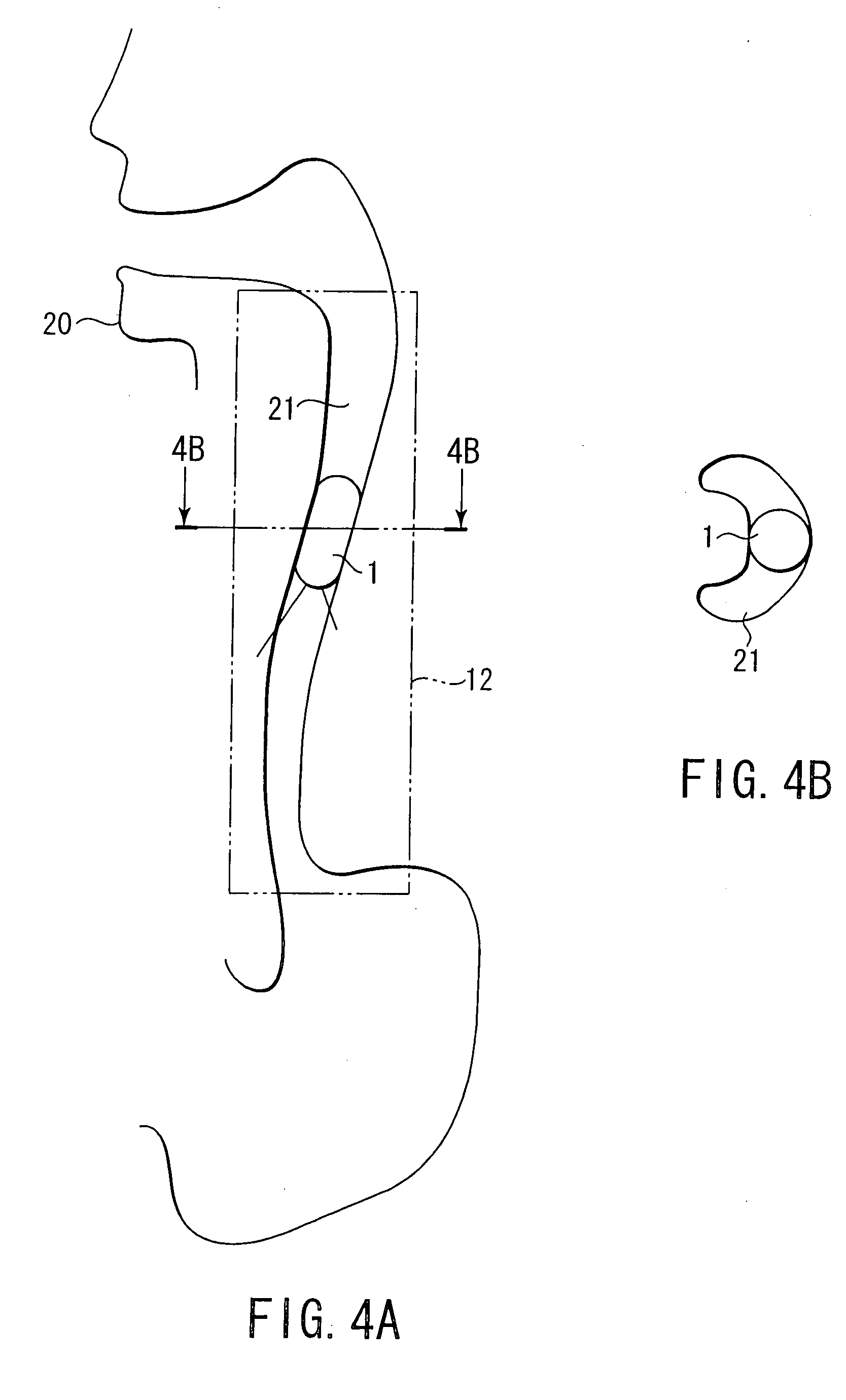
[0012] It is, therefore, possible to take many more frames of images in a shorter period of time during which the capsule passes through the esophageal canal and obtain added reliability on examination.

Problems solved by technology

However, this method needs relatively large equipment and, in addition, a large burden is inflicted on the patient and operator.
Therefore, such conventional endoscopy is hard to adopt in a first screening such as mass screening.
However, upon image transmission in realtime, the video frame rate is normally very slow at two frames per second, while, on the other hand, the time during which the capsule passes through the esophageal canal is very short, being of the order of one second.
Therefore, adequate reliability can not be ensured at such a frame rate and hence it is not suitable for the examination of the esophagus.
Further, there has been some inconvenience in that exact examination of not only the esophagus but also the internal organs such as the stomach, the duodenum the small intestine and the large intestine can not be made for any affected region of interest or its neighborhood.

Method used


Image

  • Capsule type endoscope
  • Capsule type endoscope
  • Capsule type endoscope

Examples


first embodiment

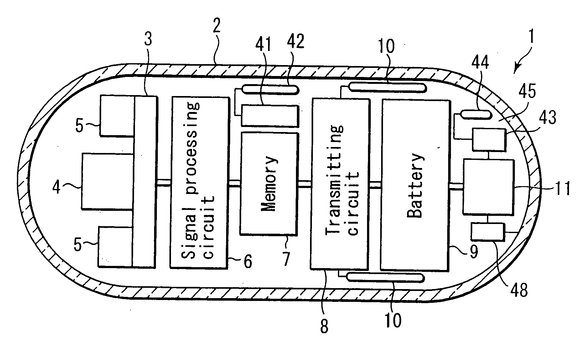
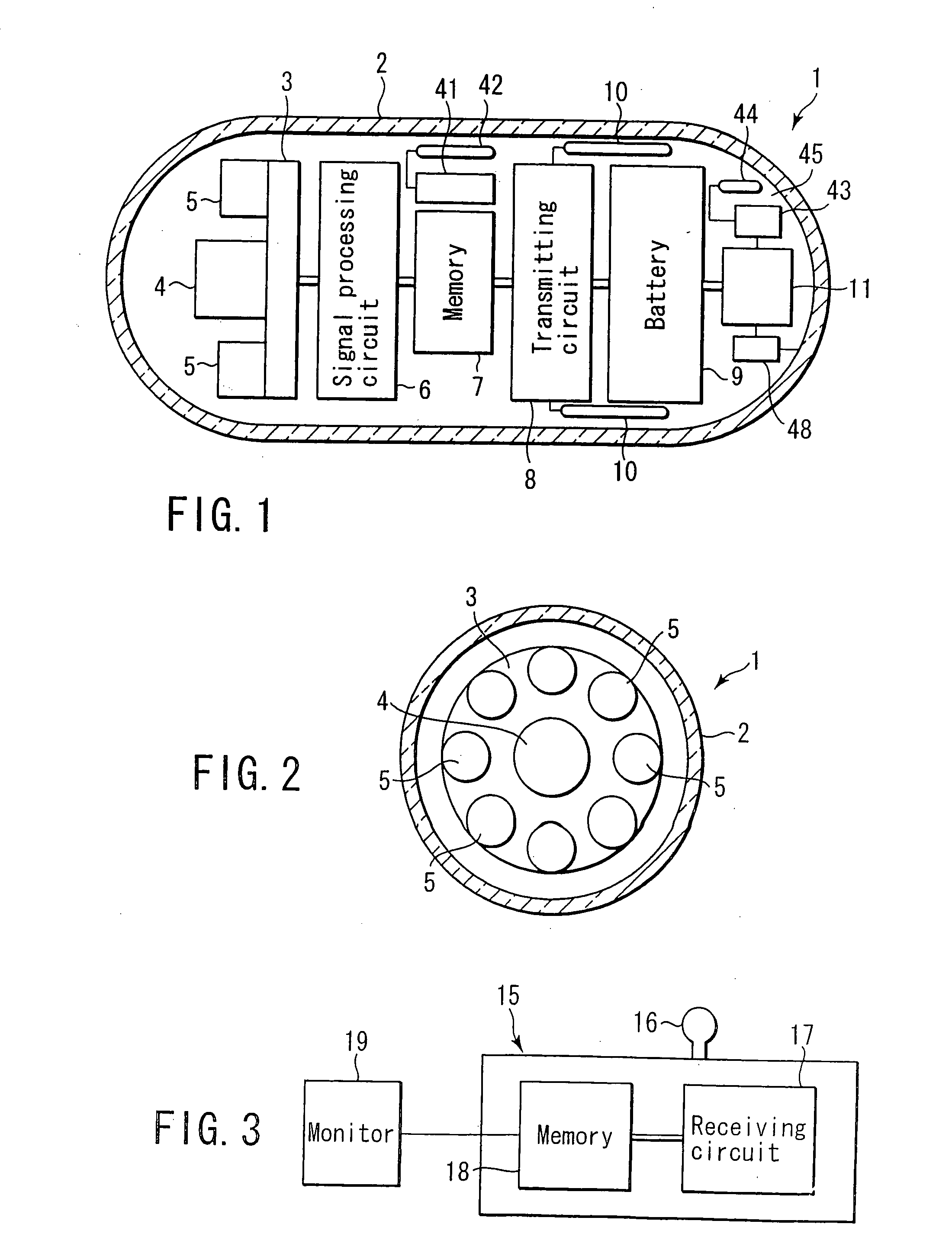
[0027] A capsule type endoscope according to a first embodiment of the present invention will be described below by referring to FIGS. 1 to 5.

[0028]FIG. 1 is a diagrammatic view showing a capsule type endoscope 1 configured as a so-called compact camera. The endoscope has a light-transparent capsule body 2 serving as a protective outer shell. The capsule body 2 is formed as a case having such an outer configuration and size that it can be passed through the esophageal canal upon being swallowed via the mouth. A sealed storage chamber is created within the capsule body 2. As shown in FIG. 1, the capsule body 2 has a cylindrical intermediate section axially elongated compared with its diameter. Both the opposite end sections of the capsule body 2, are each formed to have an axially outwardly extending hollow semispherical configuration with at least its outer surface smoothly formed. Since the capsule body 2 is formed as being axially elongated compared with the diameter, it can be e...

second embodiment

[0052] An explanation will be made below about a capsule type endoscope according to a second embodiment of the present invention by referring to FIG. 6. The capsule type endoscope 1 of this invention includes a built-in timer 31 in a capsule body 2, and, by means of this timer 31, the image taking time and the times of image taking by an image taking device, and so on, are controlled based both on its time data and according to a timer program. The remaining structure is the same as that of the first embodiment.

[0053] Based on the time data of the timer 31 and according to the timer program, the image taking time, the times of image taking, and so on, can be controlled and, by doing so, various modes of image taking can be adopted. For example, the capsule type endoscope 1, after being passed through the esophageal canal 21, is discharged via the anus past the stomach, the small intestine and the large intestine but it takes a whole day and night, unlike the passage of the capsule...

third embodiment

[0054] An explanation will be made below about a capsule type endoscope according to a third embodiment of the present invention by referring to FIG. 7. In the capsule type endoscope 1 according to this embodiment, the center of gravity, W, is located at or near a position corresponding to the image pickup element 4. Here, it is located on a longitudinal axis of the capsule body 2 at a position where the substrate 3 is situated. That is, the center of gravity, W, of the capsule type endoscope 1 is located at a forward site of the capsule body 2 on the image pickup element 4 side. The position of gravity, W is determined depending upon the shape and material of the capsule body 2 as well as the size and number of built-in component parts and their locations, and so on, and it is determined from the standpoint of these design considerations.

[0055] Since the center of gravity, W, of the capsule type endoscope 1 is located at the forward site of the capsule body 2 on the image pickup e...


PUM


Abstract

A capsule-type endoscope comprising a capsule body, an image pickup element, illuminating elements, an image signal processing circuit, a memory, an image information transmitting circuit and an antenna for wireless transmission. The capsule body contains the pickup element, the illuminating elements, the processing circuit, the memory, transmitting circuit and the antenna. While the capsule body remains in a living body, the image pickup element takes images of an interior of the living body. The processing circuit processes the image, generating image information. The memory stores the information. The transmitting circuit reads the information and supplies it to the antenna. The antenna transmits the information by radio, from the living body.

Description

CROSS-REFERENCE TO RELATED APPLICATIONS [0001] This application is based upon and claims the benefit of priority from the prior Japanese Patent Application No. 2001-186827, filed Jun. 20, 2001, the entire contents of which are incorporated herein by reference. BACKGROUND OF THE INVENTION [0002] 1. Field of the Invention [0003] The present invention relates to a capsule type endoscope having a capsule body internally equipped with an image taking device for taking images in the body cavity of a human subject. [0004] 2. Description of the Related Art [0005] An endoscope can be inserted into the esophageal canal of the human subject to directly examine the inner wall of any affected region of interest with high reliability. However, this method needs relatively large equipment and, in addition, a large burden is inflicted on the patient and operator. Therefore, such conventional endoscopy is hard to adopt in a first screening such as mass screening. [0006] As a first screening such as ...

Claims


Application Information

Patent Timeline
Patent Type & Authority Applications(United States)
IPC IPC(8): A61B1/05A61B5/07
CPCA61B1/00016A61B1/041A61B1/042A61B5/07A61B1/0676A61B1/0684A61B5/06A61B1/0607A61B5/062
Inventor MIZUNO, HITOSHI
Owner OLYMPUS CORP
Learn More