System and method for RF-induced hyperthermia

a transmitter and receiver technology, applied in the field of radio frequency (rf) circuits, can solve the problems of increasing temperature and vibration of molecules

Inactive Publication Date: 2005-11-10
AKESOGENX
View PDF88 Cites 153 Cited by
  • Summary
  • Abstract
  • Description
  • Claims
  • Application Information

AI Technical Summary

Benefits of technology

[0010] In accordance with yet another embodiment of the present invention, a method of inducing hyperthermia in at least target cells of a patient is provided. The methodology includes providing an RF transmitter, generator and transmission head. It also includes providing an RF receiver, resonant circuit and reception head. Providing antibodies bound to an RF absorption enhancer and injecting the antibodies into the patient. Waiting for a period of time for the antibodies to bind to at least one type of cells within the target area and transmitting an RF signal from the transmission head to the reception head thereby warming the specific target area.
[0011] In accordance with still yet another embodiment of the present invention, a method of inducing hyperthermia in at least target cells of a patient is provided. The methodology includes extracting target cells from the patient. Providing an RF transmitter, generator and transmission head. It also includes providing an RF receiver, resonant circuit and reception head. Providing antibodies bound to an RF absorption enhancer and introducing the antibodies to the extracted target cells. Waiting for a period of time for the antibodies to bind to at least one of the extracted target cells and transmitting an RF signal from the transmission head to the reception head thereby warming the target cells.

Problems solved by technology

When RF radiation is absorbed by matter it causes molecules to vibrate, which in turn causes heating.
Water molecules lose rotational energy via friction with other molecules, which causes an increase in temperature.
RF ablation has several drawbacks, including the fact that treatment involves direct contact with the patient, i.e., insertion of a needle-like antenna into the patent for the duration of the procedure, which can require sedation and possibly an overnight stay in a hospital.

Method used


Image

  • System and method for RF-induced hyperthermia
  • System and method for RF-induced hyperthermia
  • System and method for RF-induced hyperthermia

Examples


Embodiment Construction

[0020] In the accompanying drawings which are incorporated in and constitute a part of the specification, exemplary embodiments of the invention are illustrated, which, together with a general description of the invention given above, and the detailed description given below, serve to example principles of the invention.

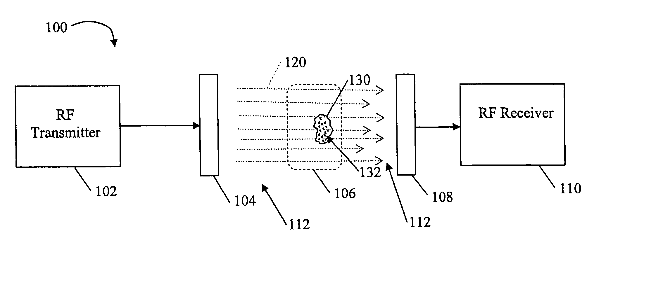
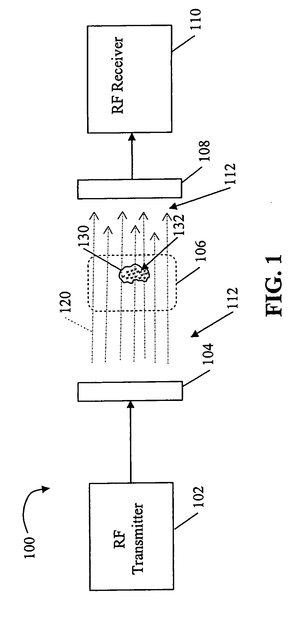
[0021] Referring to the drawings, and initially to FIG. 1, there is shown a first exemplary embodiment of a non-invasive RF system 100 for inducing hyperthermia in a target area 106. System 100 comprises an RF transmitter 102 in circuit communication with a transmission head 104 and an RF receiver 110 in circuit communication with a reception head 108. “Circuit communication” as used herein is used to indicate a communicative relationship between devices. Direct electrical, optical, and electromagnetic connections and indirect electrical, optical, and electromagnetic connections are examples of circuit communication. Two devices are in circuit communication if a sig...


PUM


Abstract

An embodiment of a non-invasive RF system for inducing hyperthermia in a target area, and a corresponding non-invasive RF method for inducing hyperthermia in a target area are provided. The system includes an RF transmitter and transmission head, and RF receiver and reception head wherein the transmission and reception heads are arranged proximate a target area so that an RF signal between the heads induces hyperthermia in the target area. The method includes arranging the transmission head and reception head proximate and on either side of a target area and transmitting an RF signal through the target area.

Description

CROSS REFERENCE TO RELATED APPLICATIONS [0001] This application claims priority to, and the benefits of, provisional application Ser. No. 60 / 569,348 filed on May 7, 2004, which is also entitled System and Method For Rf-Induced Hyperthermia, and is incorporated herein by reference.FIELD OF THE INVENTION [0002] The present invention relates generally to the field of radio frequency (RF) circuits, and more specifically to an RF transmitter and receiver system and method for inducing hyperthermia in a target area. BACKGROUND OF THE INVENTION [0003] Hyperthermia is characterized by a very high fever, especially when induced artificially for therapeutic purposes. It is known in the art to use contact antennas to direct RF electromagnetic radiation to intentionally induce hyperthermia in human tissue for therapeutic purposes, e.g., destroying diseased cells. There are also RF heating devices known in the art (e.g., the Thermotron RF-8 system, Yamamoto Viniter Co. of Osaka, Japan, and the 3...

Claims


Application Information

Patent Timeline
Patent Type & Authority Applications(United States)
IPC IPC(8): A61B18/12A61F2/00A61N1/40
CPCA61N1/406A61B18/12
Inventor KANZIUS, JOHN
Owner AKESOGENX
Why Eureka
Try Eureka