Adjustable hinge structure

a hinge structure and adjustable technology, applied in the direction of wing accessories, machine supports, manufacturing tools, etc., can solve the problems of inability to close or open the door, look in bad shape, etc., and achieve the effect of easy adjustmen

Inactive Publication Date: 2005-11-17
LIU HSU NAN
View PDF10 Cites 14 Cited by
  • Summary
  • Abstract
  • Description
  • Claims
  • Application Information

AI Technical Summary

Benefits of technology

[0007] It is another objective of the present invention to provide an adjustable hinge structure, which provides a fine adjustment when it is out of alignment, so as to prevent from drilling holes anew.
[0008] It is another objective of the present invention to provide an adjustable hinge structure, which is easy to make an adjustment.

Problems solved by technology

Mounting the hinge to the door requires drilling holes in a precision position, or the door cannot be closed or opened.
The holes left on the door make the looking in bad shape.

Method used


Image

  • Adjustable hinge structure
  • Adjustable hinge structure
  • Adjustable hinge structure

Examples


Embodiment Construction

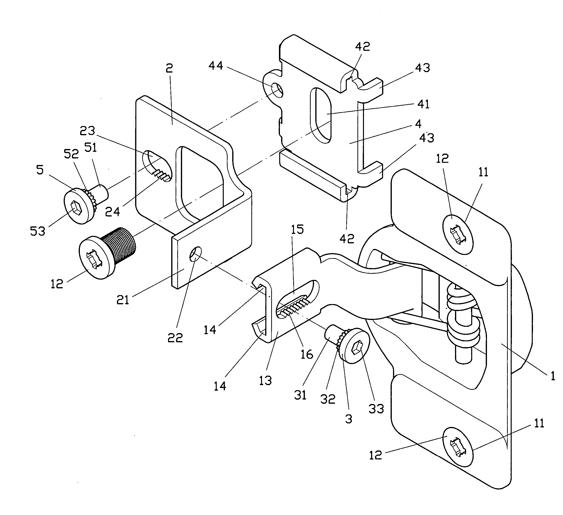
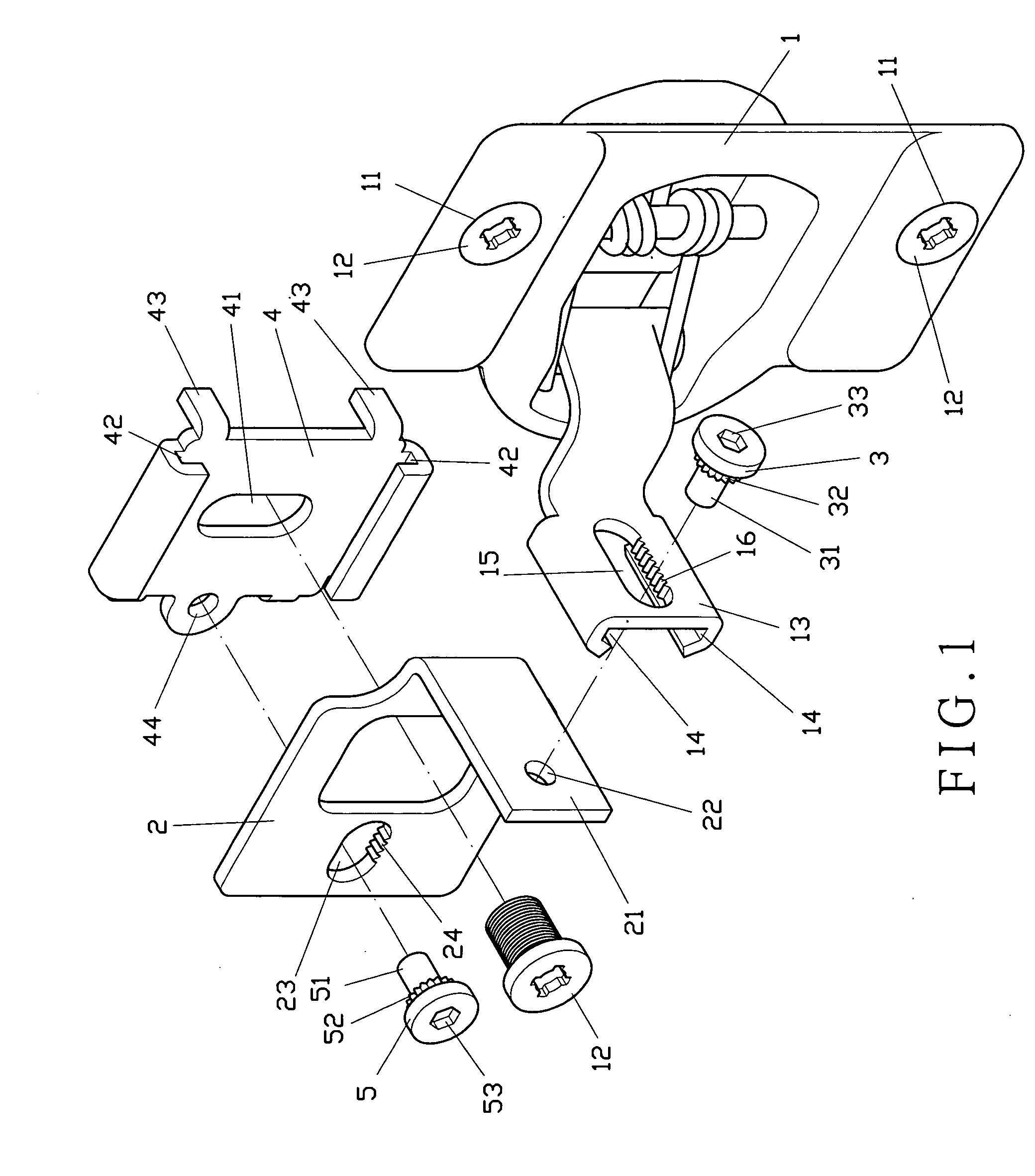
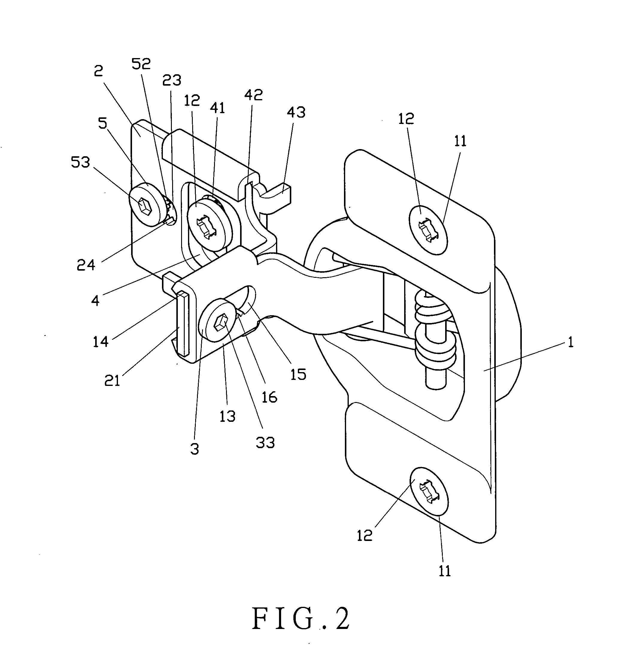
[0016] As shown in FIG. 1, the present invention comprises a fixture 1, a bracket 2, a first adjusting element 3, a securing plate 4, and a second adjusting element 5.

[0017] The fixture 1 comprises a pair of holes 11 at the top and the bottom ends for a pair of bolts 12 to insert there through. A connecting plate 13 is pivotally connected to one side of the fixture 1. The connecting plate 13 has a pair of first slots 14 on the top and the bottom ends thereof. The connecting plate 13 is formed with a first hole 15 having teeth 16 on one inner edge thereof.

[0018] The bracket 2 comprises a side block 21 to be inserted into the first slots 14 of the connecting plate 13 of the fixture 1. The side block 21 comprises a first through hole 22. The bracket 2 is formed with a second hole 23 having teeth 24 on one inner edge thereof.

[0019] The first adjusting element 3 is inserted into the first hole 15 of the connecting plate 13 and the first through hole 22 of the side block 21. The first ...


PUM


Abstract

An adjustable hinge structure includes a fixture, a bracket, a first adjusting element, a securing plate and a second adjusting element. The fixture comprises a connecting plate for the bracket to be secured thereon. A securing end of the first adjusting element is inserted through a first hole of the connecting plate and a first through hole of the bracket to adjust the position of the bracket with respect to the fixture. The securing plate is pivotally connected to the bracket, with the second adjusting element inserting through a second hole of the bracket and a second through hole of the securing plate to adjust the position of the bracket with respect to the securing plate.

Description

BACKGROUNF OF THE INVENTION [0001] 1. Field of the Invention [0002] This invention relates to an adjustable hinge structure, and more particularly to a hinge using a pair of adjusting elements to adjust the positions of a bracket with respect to a fixture and a securing plate, respectively. [0003] 2. Description of the Prior Art [0004] Most closets use hinges to open or to close their doors. Mounting the hinge to the door requires drilling holes in a precision position, or the door cannot be closed or opened. It is necessary to release the hinges first and then to drill holes anew. The holes left on the door make the looking in bad shape. [0005] In view of this shortcoming, the inventor has derived the present invention, which facilitates installation of the hinge and is easy to operate. SUMMARY OF THE INVENTION [0006] It is the primary objective of the present invention to provide an adjustable hinge structure, which bracket is adjustable in position with respect to a fixture and a...

Claims


Application Information

Patent Timeline
Patent Type & Authority Applications(United States)
IPC IPC(8): E05D3/06E05D5/08E05D7/04E05D11/10E05F1/12F16M3/00
CPCE05D5/08E05D7/0415E05D11/1014Y10T16/5324E05D2007/0484E05F1/1215E05Y2900/20E05D2007/0469
Inventor LIU, HSU-NAN
Owner LIU HSU NAN
Why Eureka
Try Eureka