Cap removing apparatus for removing cap from tube-like container

a technology of cap removing apparatus and tube-like container, which is applied in the direction of liquid handling, applications, instruments, etc., can solve the problems of long transport path, poor operability, and long work tim

Active Publication Date: 2005-11-17
IDS CO LTD
View PDF5 Cites 16 Cited by
  • Summary
  • Abstract
  • Description
  • Claims
  • Application Information

AI Technical Summary

Benefits of technology

[0012] The object of the present invention is to provide a cap removing apparatus in which correcting the knob portion of the cap and removing the cap can be successively conducted at the same correcting position.

Problems solved by technology

However, removing caps one by one from respective test tubes by manual work has spent much time and the operability has been poor.
In the conventional removing apparatus, however, since the correction mechanism and the removing mechanism are separated from each other in the transporting direction of the test tube, the transport path is long.
As a result, a large space to provide the transport path is required and the removing apparatus cannot be made compact.
Moreover, transmission of vibration from the belt conveyor to the test tube cannot be prevented during a process in which the test tube is transported from the correcting position to the removing position.
As a result, even if the test tube is fed to the removing position, the knob portion of the cap cannot be grasped by the removing mechanism.
Therefore, the cap cannot be removed from the test tube or the operation of removing the cap cannot be automated.

Method used


Image

  • Cap removing apparatus for removing cap from tube-like container
  • Cap removing apparatus for removing cap from tube-like container
  • Cap removing apparatus for removing cap from tube-like container

Examples


Embodiment Construction

[0035] An embodiment of the present invention will be explained below with reference to the accompanying drawings.

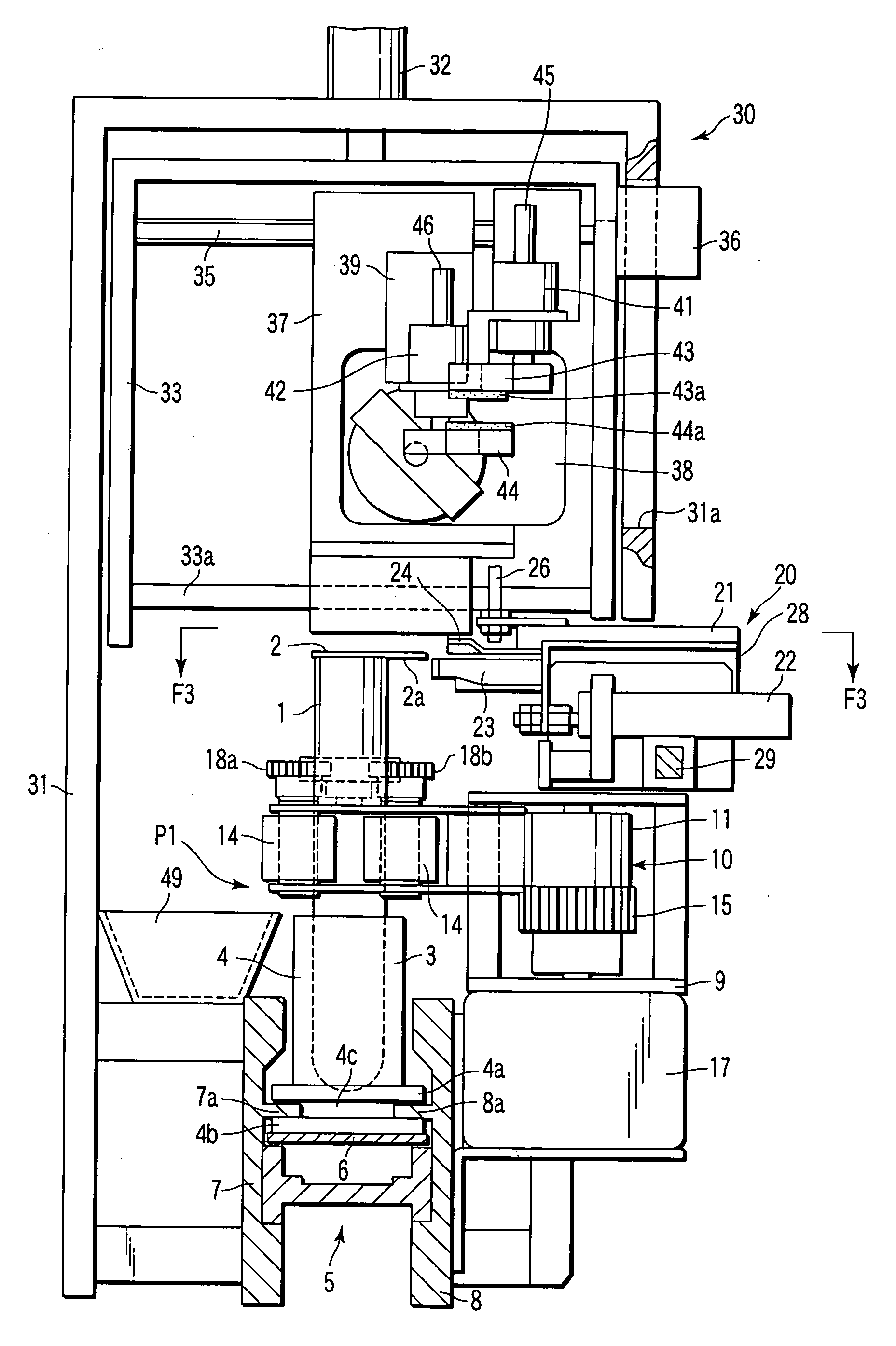
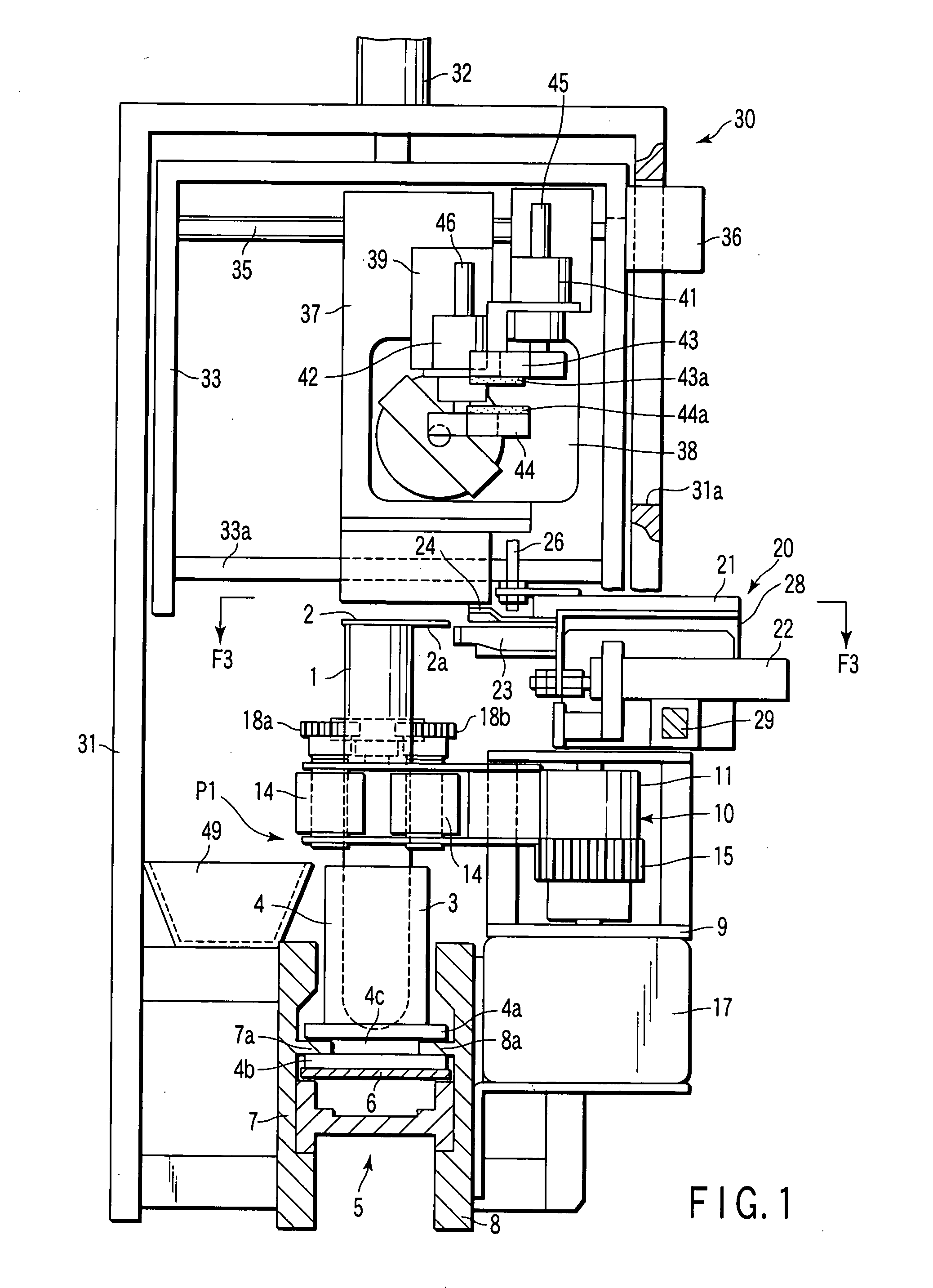
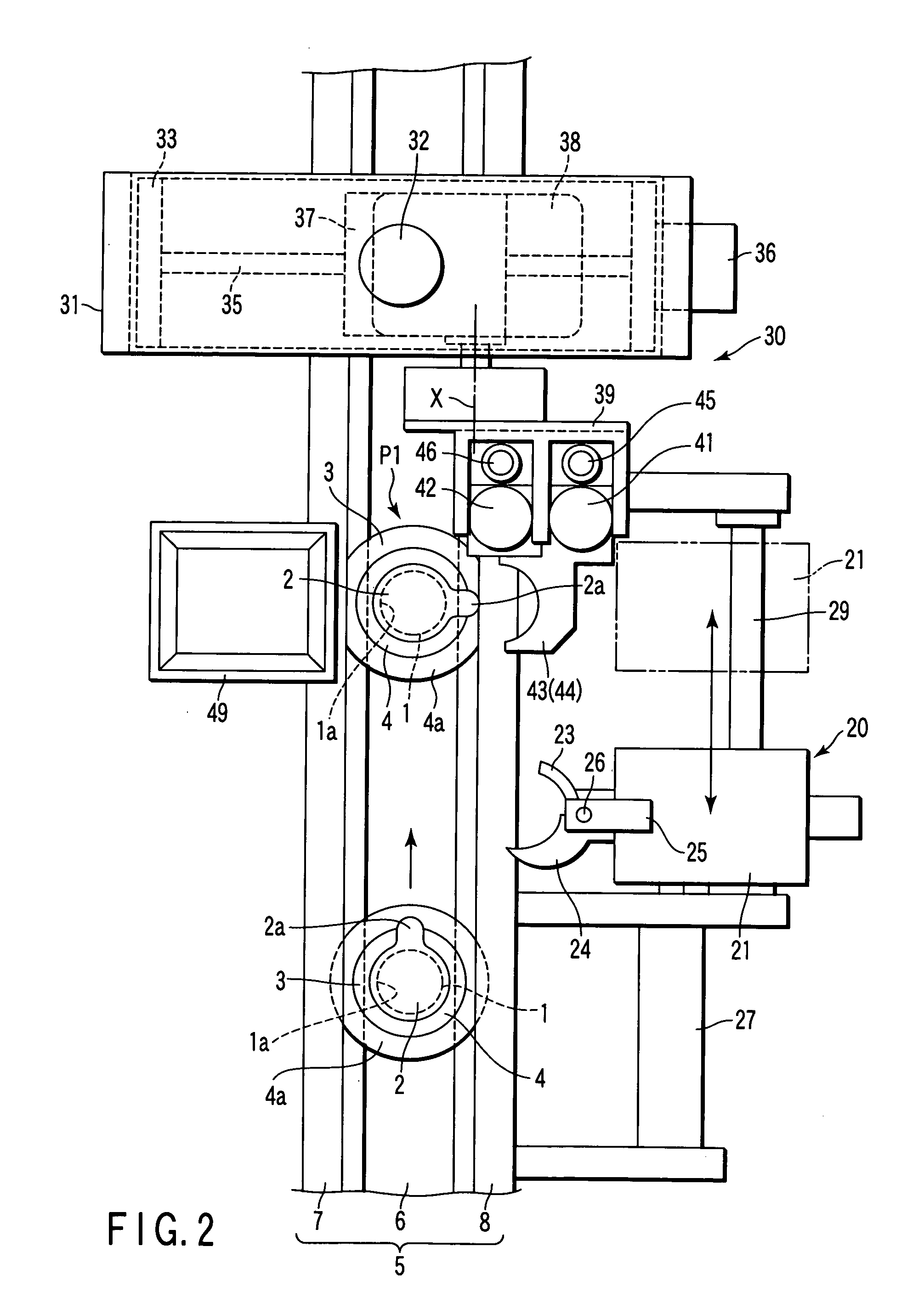
[0036]FIG. 1 to FIG. 3 show a cap removing apparatus according to the embodiment of the present invention. The apparatus comprises a holder 3 which holds a test tube 1. The test tube 1 is a tube-like container and contains, for example, a sample such as blood. The test tube 1 has an opening 1a blocked by a cap 2. The cap 2 is shaped in disk and is produced of, for example, a flexible material such as resin. The cap 2 has a knob portion 2a. The knob portion 2a expands from an outer peripheral edge of the cap 2 in a radial direction of the cap 2.

[0037] The holder 3 has a tubular portion 4 in which the test tube 1 is inserted. The tubular portion 4 supports a lower portion of the test tube 1 such that it can be rotated in a peripheral direction. Furthermore, the tubular portion 4 holds the test tube 1 in a vertically upright posture. A pair of flange portions 4a and 4b ar...


PUM

PropertyMeasurementUnit
angle of pivotingaaaaaaaaaa
angleaaaaaaaaaa
pneumatic pressureaaaaaaaaaa

Abstract

An apparatus comprises a holder which holds a container blocked by a cap, and a transport path which has a correcting position. A rotation mechanism is provided at the correcting position. When the container is rotated by the rotation mechanism, a posture of a knob portion of the cap is corrected by a correction mechanism. The corrected knob portion is grasped by a removing mechanism. The removing mechanism removes the cap from the container. The correction mechanism can be moved between a first position at which the correction mechanism advances to the correcting position and a second position at which the correction mechanism retreats from the correcting position. The removing mechanism can be moved between a third position at which the removing mechanism advances to the correcting position and a fourth position. The removing mechanism is moved to the third position when the correction mechanism retreats to the second position.

Description

CROSS-REFERENCE TO RELATED APPLICATIONS [0001] This application is based upon and claims the benefit of priority from prior Japanese Patent Application No. 2004-144796, filed May 14, 2004, the entire contents of which are incorporated herein by reference. BACKGROUND OF THE INVENTION [0002] 1. Field of the Invention [0003] This invention relates to a cap removing apparatus employed when, for example, a cap blocking an opening of a test tube is removed from the test tube and, more particularly, to a structure to correct a posture of a knob portion provided on an outer peripheral edge of the cap to a regular posture and automatically remove the cap from the opening of the test tube by grasping the knob portion. [0004] 2. Description of the Related Art [0005] For example, an opening of a test tube containing a sample such as blood is blocked by a cap. The cap is produced of a soft material such as synthetic resin and has a flange-like knob portion on an outer peripheral edge thereof. To...

Claims


Application Information

Patent Timeline
Patent Type & Authority Applications(United States)
IPC IPC(8): B65B35/58B67B7/00B67B7/12G01N35/02G01N35/04
CPCB67B7/00G01N35/02G01N35/04G01N2035/0406G01N2035/0405G01N35/00
Inventor ITOH, TERUAKI
Owner IDS CO LTD
Why Eureka
Try Eureka