
Mounting structure for resonator

Inactive Publication Date: 2005-11-17
TOYOTA JIDOSHA KK
View PDF20 Cites 2 Cited by
  • Summary
  • Abstract
  • Description
  • Claims
  • Application Information

AI Technical Summary

Benefits of technology

[0005] Accordingly, it is an objective of the present invention to provide a mounting structure of a resonator that permits a resonator to be quickly and easily mounted in a confined fender.

Problems solved by technology

This reduces the workability.

Method used


Image

  • Mounting structure for resonator
  • Mounting structure for resonator
  • Mounting structure for resonator

Examples


Embodiment Construction

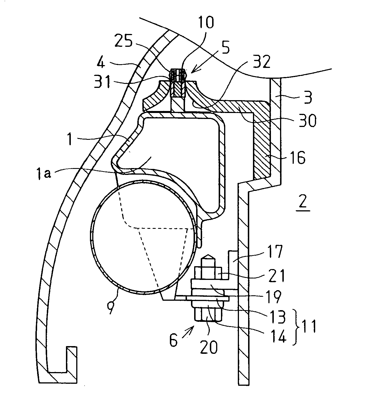
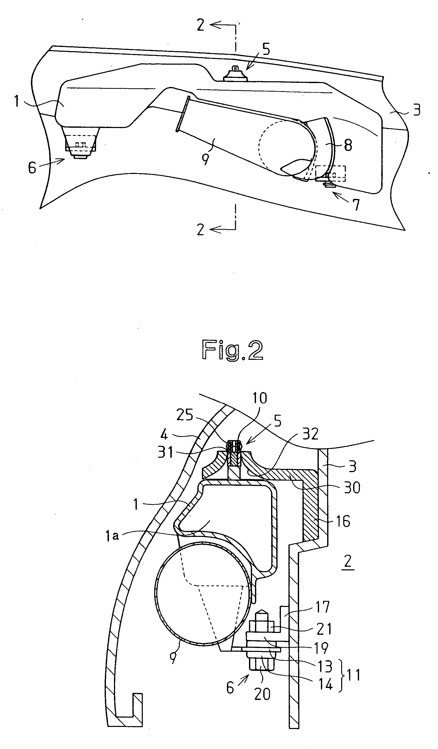
[0016] A mounting structure of a resonator in an automobile fender according to one embodiment of the present invention will now be described with reference to FIGS. 1 to 5(d).

[0017] A resonator 1 of the present embodiment functions as an intake muffler device. As shown in FIGS. 1 and 2, the resonator 1 is located in a fender 4. Specifically, the fender 4 is attached to an apron panel 3, which is a sidewall of an engine compartment 2. The fender 4 extends diagonally downward like a canopy. In the fender 4, the resonator 1 is attached to the apron panel 3 of the vehicle body with a plurality of mounting members 5, 6, 7, the number of which is three in this embodiment. In the present embodiment, the mounting member 5, which is referred to as a first mounting member, and the mounting members 6, 7, which are referred to as second mounting members, form the mounting structure for the resonator 1. The first mounting member 5 is engaged with and supports the resonator 1 in an upper portio...


PUM


Abstract

An upper bracket having a hook receiving hole is provided in an upper portion of the interior of the fender. A lower bracket having a nut is provided in a lower portion of the fender. A resonator has a pin and a bolt receiving portion. The pin has an elastic hook portion that is hooked to and supported by the upper bracket. The bolt receiving portion is fixed to the nut of the lower bracket with a bolt. The pin is inserted into the hook receiving hole so that the resonator is positioned in a hooked state. Then, the resonator is mounted in the fender by performing screwing procedure.

Description

BACKGROUND OF THE INVENTION [0001] The present invention relates to a structure for mounting a resonator in a fender of an automobile. [0002] Typically, a resonator is attached to an intake duct of an automobile engine to reduce intake noise. Conventionally, a resonator is mounted in an engine compartment or in a fender together with an intake duct. For example, Japanese Laid-Open Patent Publication No. 6-200847 discloses a resonator mounted in a fender. This resonator is advantageous in lowering the temperature of intake air. [0003]FIG. 7 is a perspective view illustrating a mounting structure of a resonator disclosed in Japanese Laid-Open Patent Publication No. 6-200847. As shown in FIG. 7, two shoulder bolts 52 are integrated with a resonator 51 by insert molding. The head of each shoulder bolt 52 is embedded in the resonator 51. Two bolt receiving holes 54 are formed in a side panel 53 that separates the interior of the fender from the engine compartment. A shaft of each bolt 52...

Claims


Application Information

Patent Timeline
IPC IPC(8): B60K13/02F02M35/10F02M35/12F02M35/16
CPCF02M35/10354F02M35/1283F02M35/1255F02M35/161
Inventor INOUE, NORITO
Owner TOYOTA JIDOSHA KK
Learn More