
Wheel axle assembly

a technology of axles and wheels, applied in the direction of hand carts, hand carts with one axis, transportation and packaging, etc., can solve the problems of difficult roll shelter, difficult to roll shelter, and inability to exchange permanent wheels for different wheels, etc., to facilitate the engagement of the clip, quick and easy mounting, and quick replacement

Active Publication Date: 2017-11-09
INT E Z UP INC
View PDF4 Cites 1 Cited by
  • Summary
  • Abstract
  • Description
  • Claims
  • Application Information

AI Technical Summary

Benefits of technology

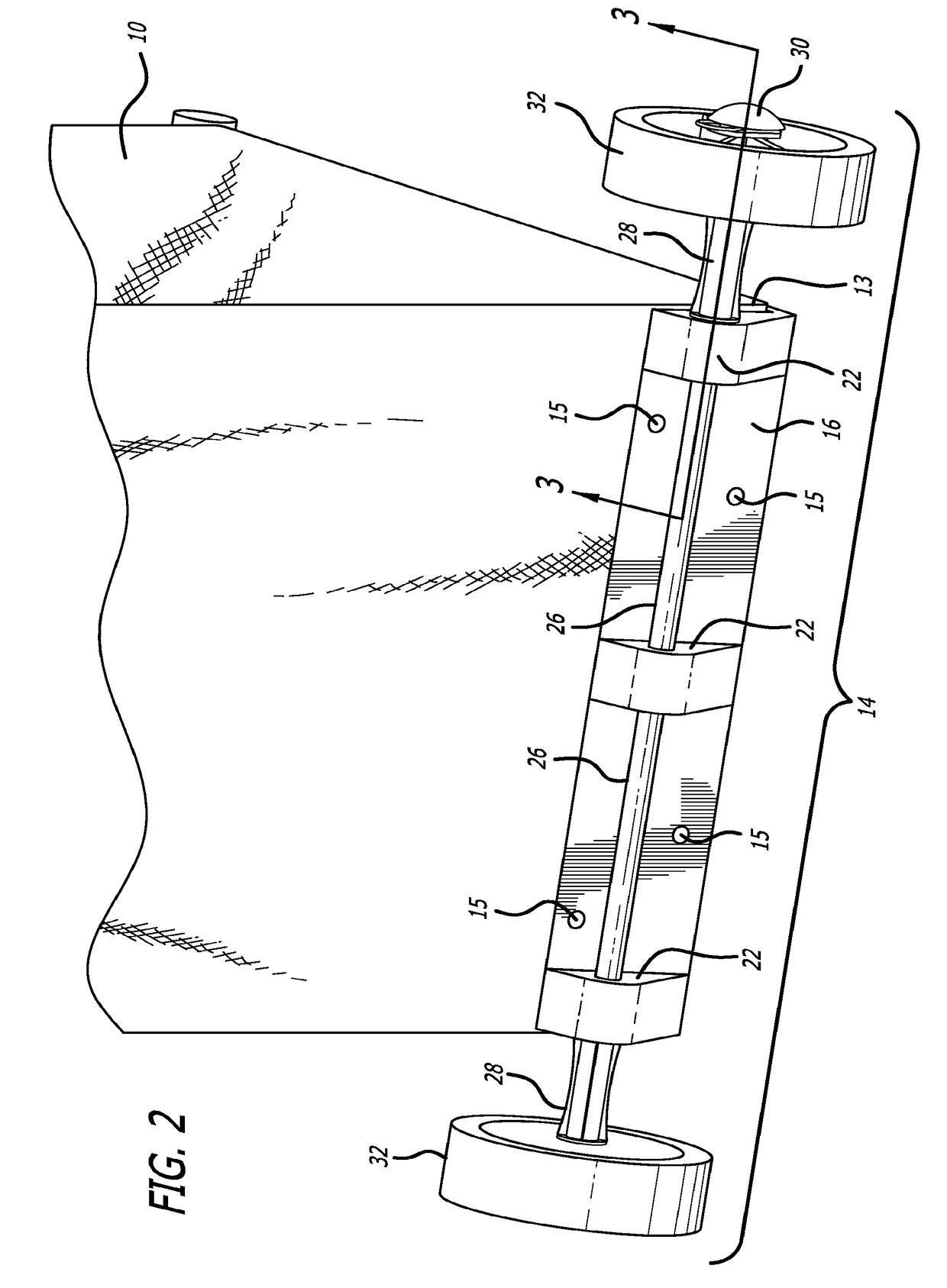
[0005]The present invention is a wheel assembly for a case or other bulk object that includes an axle that can be mounted to a fixed bracket. The bracket is attached to the bulk object such as a roller bag or carrying case, and the wheel assembly quickly and easily mounts to the bracket via bosses extending from the bracket. The axle of the wheel assembly is supported by the bosses to provide a rolling engagement that allows the attached wheels to rotate freely. The wheels in this configuration can be substantially larger, such as four to six inches or more, to better navigate uneven surfaces or problematic terrain such as sand or gravel. The wheels on the axle fix the assembly to the bracket through the bosses, such that as long as the wheels are in place the wheel assembly is reliably secured to the bracket on the bulk object. When the wheel assembly is no longer needed or an exchange of the wheels are desired, a first wheel is removed from the axle to allow the axle to be slid through and out the bosses, leaving only the bracket on the bulk object. In the case of a wheel exchange, the new wheels can be mounted on the axle and quickly replaced on the bracket.
[0006]To secure the wheels to the axle while permitting quick release, the wheels may be locked on the axle with a specialized locking cap placed over the ends of the axle. The locking cap incorporates a two stage clip that holds the wheel onto the axle when secured to the assembly. To facilitate engagement of the clip with the axle, the axle may be provided with an annular groove between the end of the axle and the outer surface of the wheel. The annular groove is engaged by the two stage clip, which may have a hairpin-like shape including a first stage having a semi-circular (or other polygonal or rounded shape) portion with a diameter / width greater than the diameter of the annular groove on the axle, and a second stage having a parallel, pinched, or necked configuration wherein opposite sides of the second stage are separated by a distance that is less than the diameter of the axle and are biased to bear against the surface of the annular groove. The two stage clip can easily be manually transitioned from a first position in which the clip is engaged with the axle at the narrowed (second stage) portion thereby fixing the wheel while simultaneously preventing the wheel from slipping off the axle, to a second position where the larger circular (first stage) portion of the clip is loosely about the axle, permitting the clip to easily slip off the axle and thereby allowing the wheel to be removed from the axle. Once a wheel is removed, the axle may be slipped through the bosses on the bracket and the entire wheel assembly separated from the bracket.

Problems solved by technology

The ease in which these shelters are expanded and contracted have led to widespread commercial success, but the shelters can be relatively heavy, weighing up to forty pounds or more.
An issue arises, however, when the permanently attached wheels must navigate some irregular terrain such as sand or uneven pavement.
The top heavy carry case can become unstable, making it difficult to roll the shelter.
Moreover, the permanent wheels cannot be exchanged for different wheels if the terrain or conditions suggest a different set.

Method used


Image

  • Wheel axle assembly
  • Wheel axle assembly
  • Wheel axle assembly

Examples


Embodiment Construction

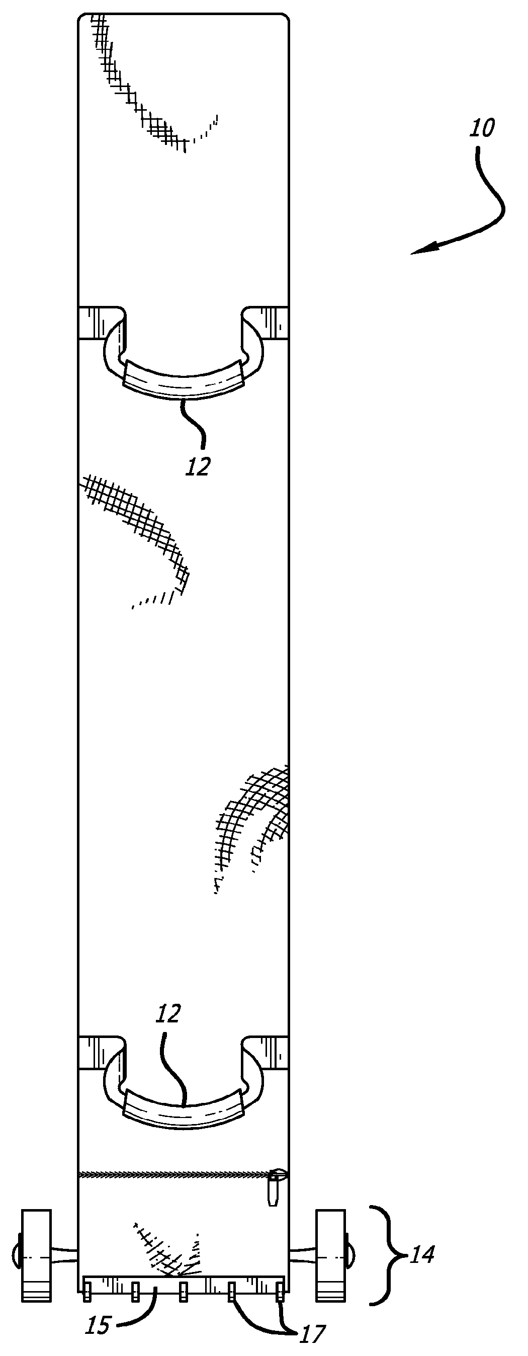
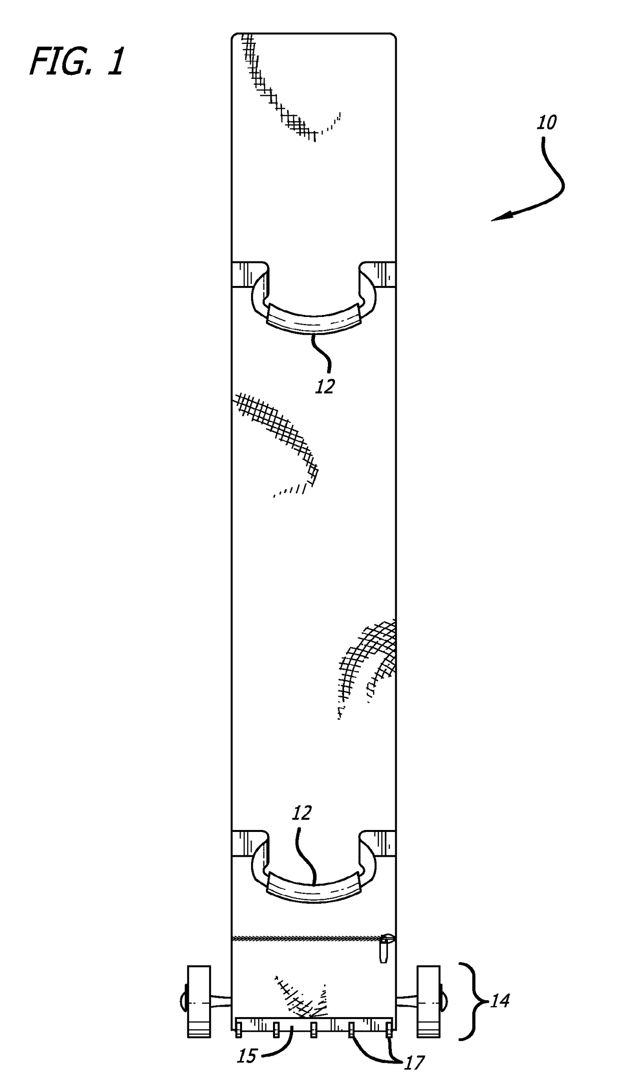
[0013]FIG. 1 depicts a case 10 for a collapsible shade station, which may be a flexible cloth material or a more resilient sturdy material (e.g., plastic, aluminum, or the like) as dictated by the needs of the user. The case 10 may include handles 12 along with a zippered opening along a top surface or bottom surface, although other closure means are possible. Also, while shown in generally a rectangular profile, the case 10 may take a number of different shapes and sizes without departing from the present invention. Along a bottom edge of the case 10 is a wheel assembly 14 that can be quickly and easily affixed to and released from the case 10 as needed using a quick-release system as described more fully below. It is to be understood that while a two-wheeled assembly is illustrated, the invention can be incorporated into multiple other wheel counts, particularly three and four wheeled variants. The case 10 preferably includes a stabilizer 15 on the opposite side of the wheel assem...


PUM


Abstract

A releasable wheel assembly includes a bracket having multiple bosses, each boss including a hole that receives an axle. A pair of wheels are mounted on the axle and a pair of locking caps fit over respective ends of the axle, the locking caps each including a clip for engaging the axle at a circumferential groove to prevent movement of the locking cap along the axle. The wheel assembly can be mounted to a carry bag or other storage unit by mounting the bracket to the storage unit, where the wheels and axle can be easily removed from the bracket.

Description

CROSS-REFERENCE TO RELATED APPLICATION[0001]The present application is a divisional of U.S. patent application Ser. No. 14 / 746,478, filed on Jun. 22, 2015, and titled “WHEEL AXLE ASSEMBLY,” the disclosure of which is expressly incorporated by reference herein in its entirety.BACKGROUND[0002]The present invention is directed to wheel axle assemblies, and more particularly to a wheel assembly for moving heavy objects over flat or uneven terrain with the capability of easily removing the wheel assembly for the purpose of changing the wheels or for storing the device.[0003]Collapsible shelters such as those offered by International E-Z Up, Inc. have become ubiquitous at parks, beaches, athletic events, and a myriad of other locations where respite from the sun and other elements is desired. These collapsible shelters are perfect for creating a covered environment during the event, and then the shelter is quickly collapsed into a compact configuration for transportation. The ease in whic...

Claims


Application Information

Patent Timeline
Patent Type & Authority Applications(United States)
IPC IPC(8): B60B35/02B62B1/18B62B1/00B60B7/00B60B3/00B60B35/04B60B7/06B62B1/26B60B37/10B60B35/00
CPCB60B2200/43B60B3/001B60B37/10B62B1/26B60B35/006B60B35/025B60B35/04B62B1/008B62B1/18B60B7/06B60B7/0013A45C5/143B62B1/12B62B5/0083B62B2205/10
Inventor CARTER
Owner INT E Z UP INC
Learn More