Pressure gauge

a pressure gauge and pressure gauge technology, applied in the field of pressure gauges, can solve the problems of air pressure upstream of compressed air pressure, no means, and variable pressure setting

Inactive Publication Date: 2005-11-17
FINISHING BRANDS UK
View PDF11 Cites 27 Cited by
  • Summary
  • Abstract
  • Description
  • Claims
  • Application Information

AI Technical Summary

Benefits of technology

[0009] In a first aspect, the invention provides a retrofittable pressure gauge for a spray gun comprising a pressure sensor, located in a pressure chamber, a power source and a display unit, all enclosed within a case, a passageway providing fluid communication between the pressure chamber and a pressurised interior space of a spray gun when the gauge is mounted on a spray gun and a means for attachment to a spray gun, wherein the means for attachment comprises a mounting fixture configured for mounting the pressure gauge at a spreader valve or a trigger operated fluid valve of

Problems solved by technology

One problem associated with the aforementioned arrangements of air pressure gauge and compressed air spray gun is that the location of the air pressure gauge is such that the air pressure upstream of the compressed air pressure reducing valve is measured.
It is possible for a compressed air inlet pressure reducing valve to be included as part of the spray gun thus eliminating the n

Method used


Image

  • Pressure gauge
  • Pressure gauge
  • Pressure gauge

Examples


Embodiment Construction

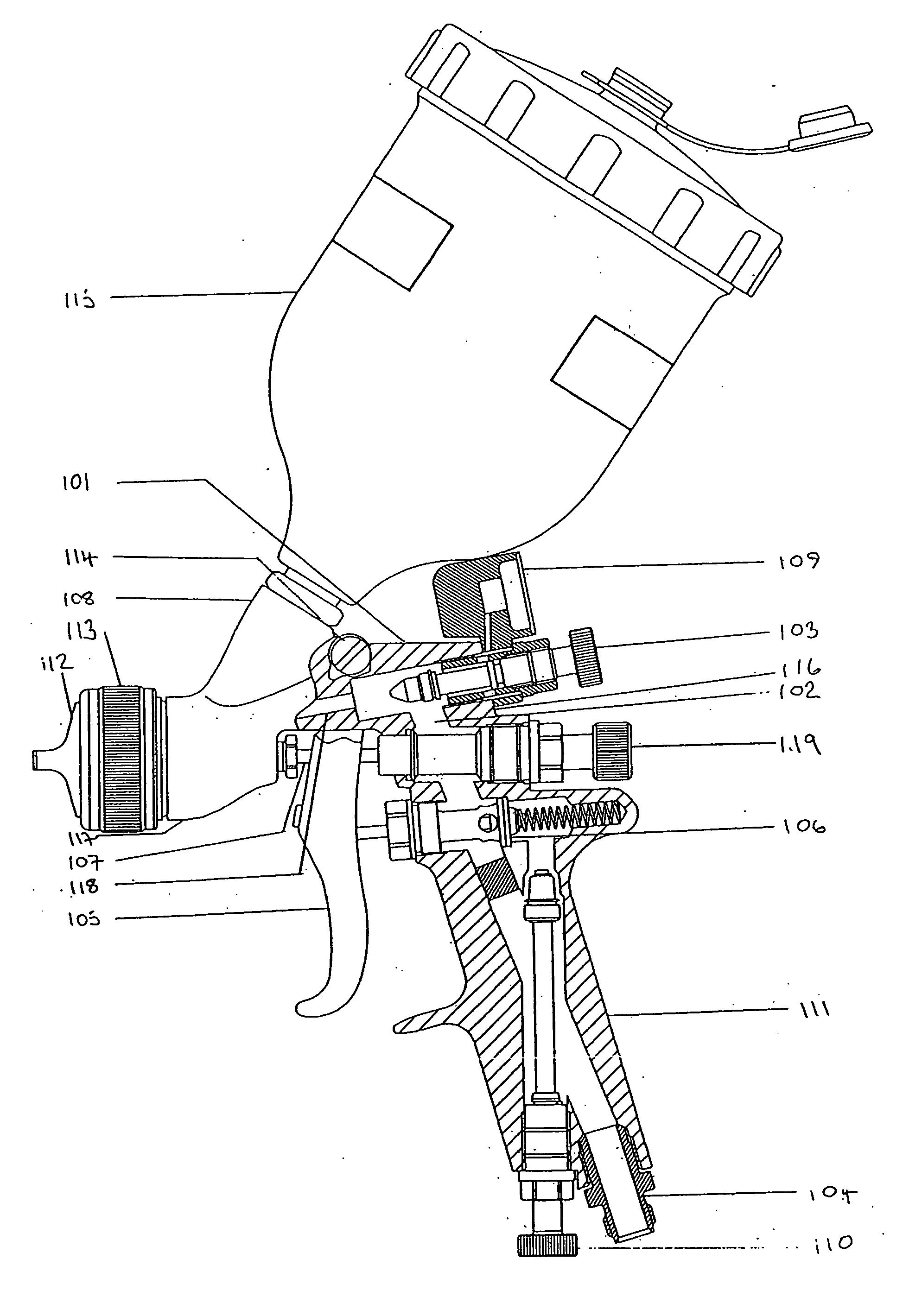
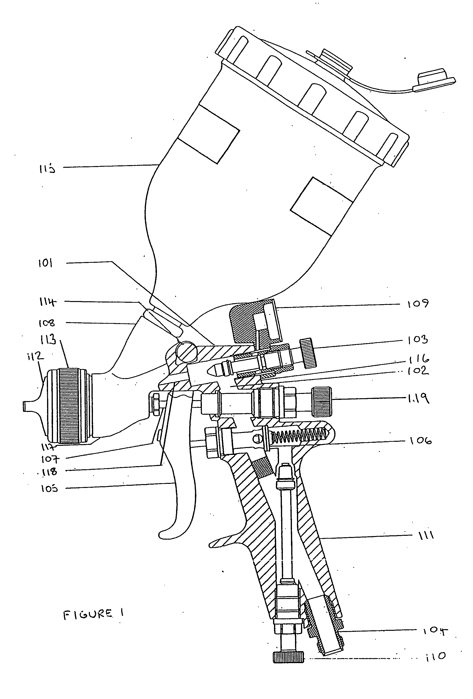
[0023]FIG. 1 shows a spray gun comprising a gun body 101, defining an interior space 102 through which compressed air can be passed, having an integral handle 111 depending from adjacent a first end of the gun body 116 and an air cap 112 secured to an opposing second end of the gun body 117 by a retaining ring 113.

[0024] A trigger 105 is secured to the gun body 101 by a screw 114 to pivot towards the handle 111 when manually squeezed to turn on the spray gun. A fluid reservoir 115 is reversibly attached to a fluid inlet 108 protruding from an upper part of the gun body 101. A compressed air hose (not shown) is reversibly attached to a compressed air inlet 104 located on an end of the handle 111 remote from the gun body 101.

[0025] The volume of compressed air entering the spray gun is controlled by a compressed air inlet pressure reducing valve 110 operating within the handle 111 of the spray gun. During use, as the trigger 105 is manually squeezed, compressed air from the compress...


PUM


Abstract

A retrofittable pressure gauge for a spray gun includes a pressure sensor, located in a pressure chamber, a power source and a display unit, all enclosed within a case, a passageway providing fluid communication between the pressure chamber and a pressurised interior space of the spray gun when the gauge is mounted on the spray gun and a mounting fixture configured for mounting the pressure gauge at a spreader valve or a trigger operated fluid valve of the spray gun.

Description

[0001] This invention relates to an air pressure gauge, preferably a digital air pressure gauge, adapted to be retrofitted to a compressed air spray gun and a compressed air spray gun comprising the said air pressure gauge. In particular the invention discloses an air pressure gauge adapted to be retrofitted to a compressed air spray gun at a location down stream of a compressed air inlet pressure reducing valve or trigger operated shut off valve. BACKGROUND TO THE INVENTION [0002] Traditionally the compressed air inlet pressure of a compressed air spray gun is adjusted to suit a particular compressed air spray gun air cap or spraying medium by a compressed air pressure reducing valve and air pressure gauge mounted upstream of the compressed air inlet, mounted either adjacent to the source of the compressed air near a spray booth or mounted pendant of the handle of the compressed air spray gun. One problem associated with the aforementioned arrangements of air pressure gauge and com...

Claims


Application Information

Patent Timeline
IPC IPC(8): B67D7/56B05B1/00B05B7/02B05B7/04B05B7/08B05B7/12B05B7/24B05B9/01B05B12/00B05B12/08B05B15/00F25C3/04G01L19/00G01L19/14
CPCB05B7/0815B05B7/12B05B7/2402G01L19/14B05B12/008G01L19/0007B05B7/2478
Inventor ROGERS, JOHN ANTHONY
Owner FINISHING BRANDS UK
Why Eureka
Try Eureka