Simplified linear recliner having a fixed pawl

a linear recliner and fixed pawl technology, applied in the direction of chairs, vehicle components, vehicle arrangements, etc., can solve the problems of overcoming the assembly capability, the seatback of an unoccupied seat may tend to oscillate, and the seatback of an unoccupied seat can move a small amount, so as to reduce the stacking of tolerances and reduce the stacking. , the effect of compact construction

Inactive Publication Date: 2005-11-17
BONK JEFFERY T
View PDF10 Cites 0 Cited by
  • Summary
  • Abstract
  • Description
  • Claims
  • Application Information

AI Technical Summary

Benefits of technology

[0011] A further advantage of the present invention is a simple, compact construction that reduces tolerance stack-up that would otherwise result in significant seat back chucking.
[0012] Additionally, packaging and trim of the overall seat assembly is more easily achieved because the recliner assembly's moving parts are internal to the compact housing.
[0013] Additional advantages and features of the present invention will become apparent from the subsequent description and the appended claims, taken in conjunction with the accompanying drawings.

Problems solved by technology

The recliner assembly in a vehicle seat is quite small when compared with the length of a seatback, and vehicle vibration or movement of an occupant may impose various forces upon that lever arm during use.
Because these forces are applied along such a lengthy lever arm, they can impose a large moment about the recliner assembly's pivot point potentially overcoming the capability of the assembly to anchor the seatback.
In addition, any imperfections in the components of the recliner assembly, such as play or backlash between the engaging teeth or tolerances in the assembly components, may allow the seatback to move a miniscule amount even when the assembly is locked.
For example, the seatback of an unoccupied seat may tend to oscillate when the vehicle encounters rough road conditions.

Method used


Image

  • Simplified linear recliner having a fixed pawl
  • Simplified linear recliner having a fixed pawl
  • Simplified linear recliner having a fixed pawl

Examples


Embodiment Construction

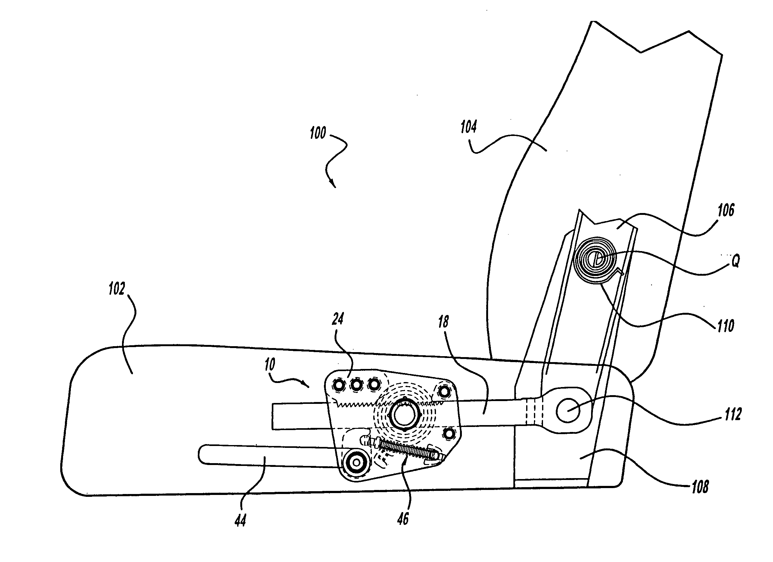
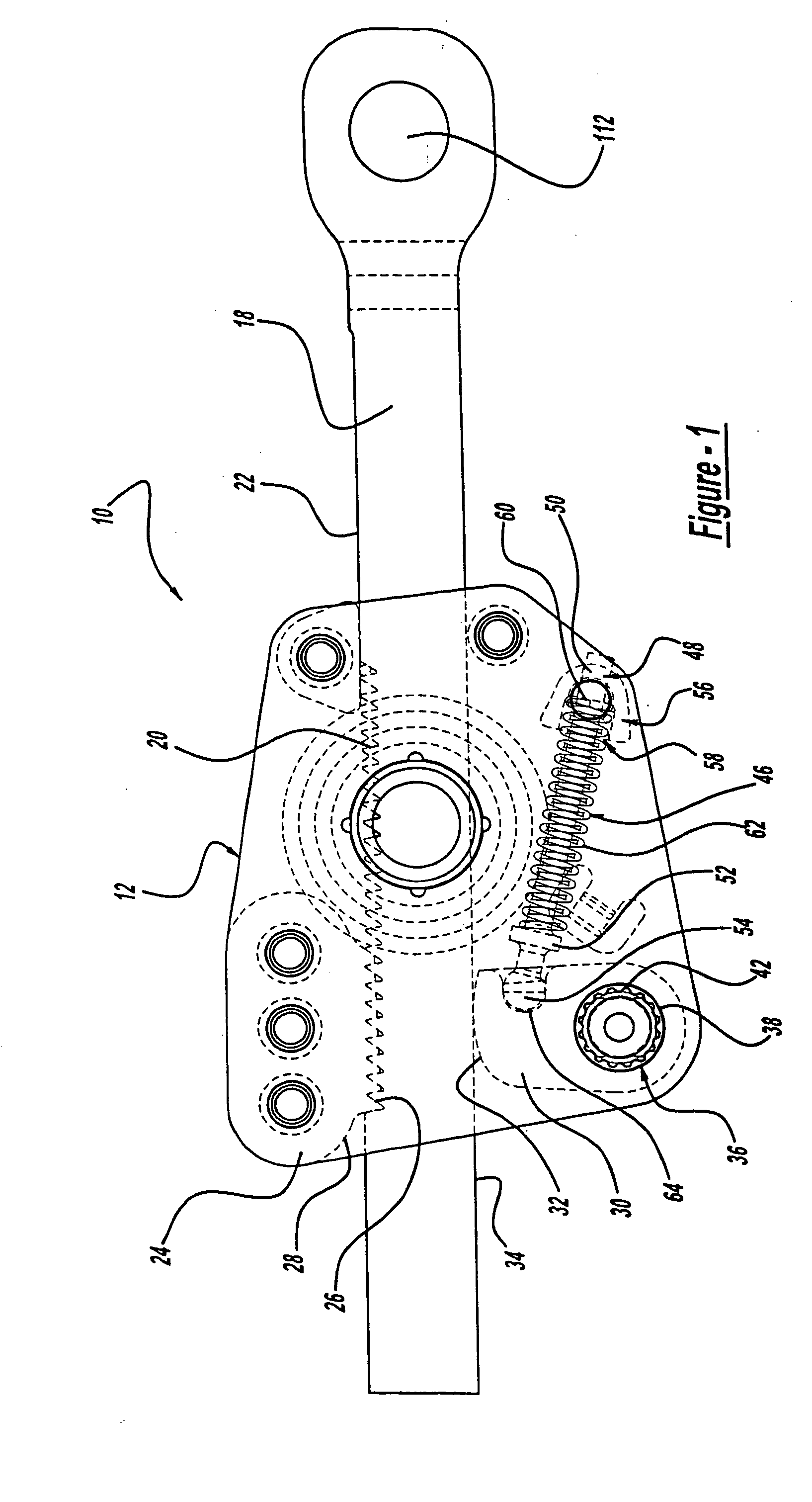
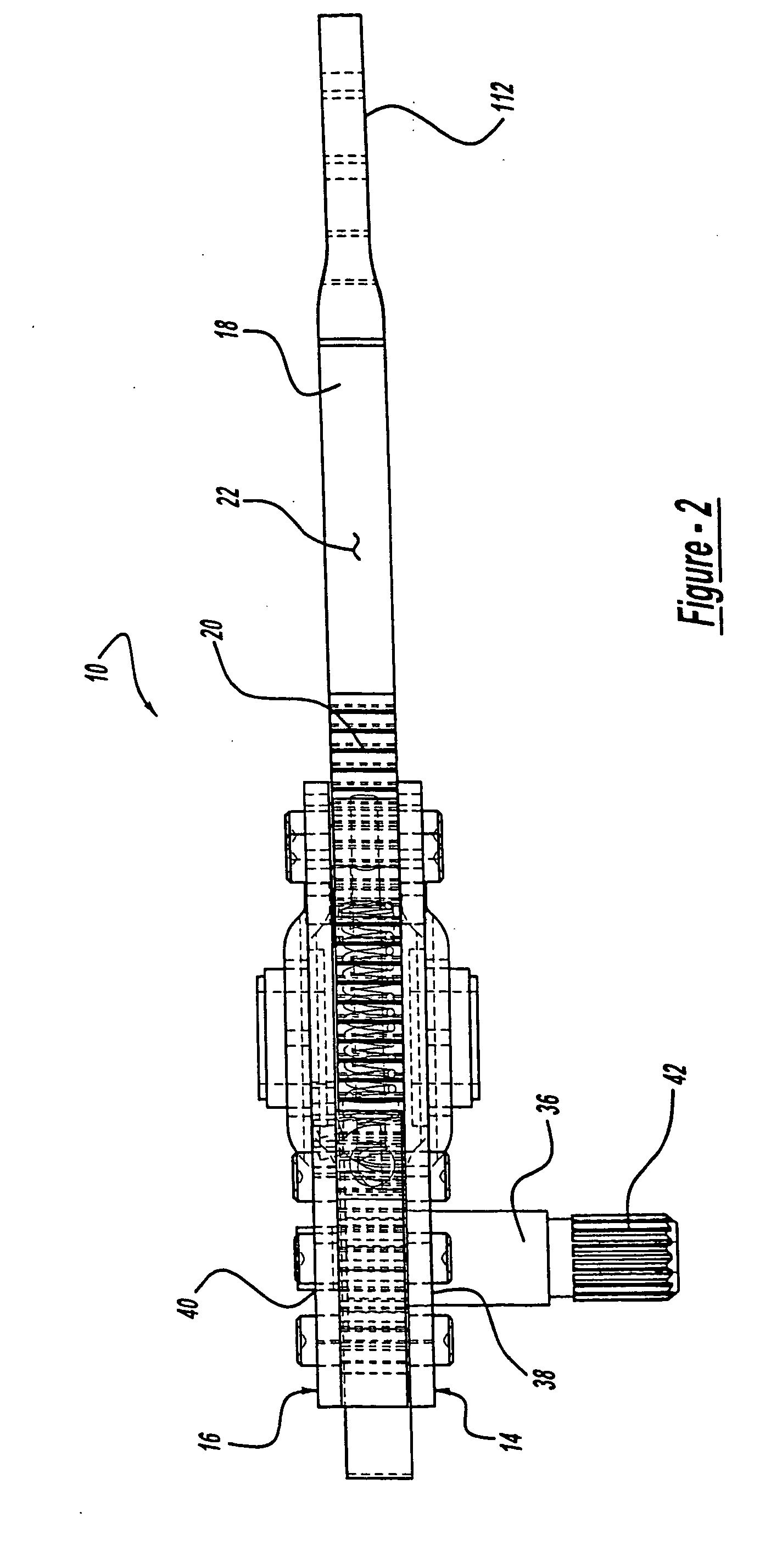
[0019] With reference to FIGS. 1 through 3, a preferred embodiment of a linear recliner assembly 10 will be described in detail. The linear recliner assembly 10 includes a housing 12 that includes a first support plate 14 and a second support plate 16. A recliner rod 18 is slidably supported within the housing 12 and includes a toothed rack 20 formed in a top face 22. A pawl 24 is supported within the housing 12 and has a tooth portion 26 on a surface 28 facing the toothed rack 20 of the reclining rod 18. The pawl 24 is fixed between the first and second support plates 14,16 to prohibit pivoting or other movement relative to the housing 12. A cam 30 is rotatably supported between the first and second support plates 14,16 and has a cammed surface 32 that contacts a bottom face 34 of the recliner rod 18. The cam 30 is fixed for rotation with a spindle 36, which is rotatably supported by the first and second support plates 14,16 through respective openings 38,40. The spindle 36 include...


PUM


Abstract

A linear recliner assembly is provided having a recliner rod slidably supported within a housing. The recliner rod is selectively engageable with a pawl which is fixed within the housing. The recliner rod is in contact with a cam which is operable to force the recliner rod into engagement with the pawl or enable the recliner rod to fall out of engagement with he pawl. The cam is biased in a first position by a biasing mechanism, such that the recliner rod is engaged with the pawl. The linear recliner assembly is implemented into a seat assembly for enabling an operator to select a plurality of recline positions of a seat back relative to a seat.

Description

CROSS-REFERENCE TO RELATED APPLICATIONS [0001] This application is a continuation of U.S. patent application Ser. No. 10 / 614,541 filed on Jul. 7, 2003, which is a divisional of U.S. patent application Ser. No. 09 / 748,482 filed on Dec. 27, 2000 (now U.S. Pat. No. 6,655,741). The disclosure of the above application is incorporated herein by reference.FIELD OF THE INVENTION [0002] The present invention relates to linear recliner assemblies and more particularly to a linear recliner assembly having a fixed pawl. BACKGROUND OF THE INVENTION [0003] Occupant safety and comfort are paramount concerns for automobile manufacturers. In particular, vehicle seating systems are a significant focus for improved comfort and safety. Conventional vehicle seating systems include reclining seats that enable comfort adjustment by a vehicle occupant. [0004] In reclining seats, a recliner assembly is mounted to a long lever arm, namely the seat back, against which various forces are applied. The recliner ...

Claims


Application Information

Patent Timeline
Patent Type & Authority Applications(United States)
IPC IPC(8): B60N2/22A47C1/026B60N2/02B60N2/23B60N2/90
CPCB60N2/443B60N2/23B60N2/929
Inventor BONK, JEFFERY T.
Owner BONK JEFFERY T
Why Eureka
Try Eureka