Induction motor capable of being housed in a tubular actuator and method of assembling this motor

Active Publication Date: 2014-11-06
SOMFY ACTIVITES SA
View PDF15 Cites 0 Cited by
  • Summary
  • Abstract
  • Description
  • Claims
  • Application Information

AI Technical Summary

Benefits of technology

[0010]Therefore, the present invention aims to overcome some or all of these drawbacks by providing an induction motor all

Problems solved by technology

Their deterioration, during or after assembly, due in particular to the axial abutment of a component against the stator, may cause motor malfunction.
However, the presence of said protection element tends to move away the bearings used to ensure the rotation of the rotor.
It can therefore increase eccentricity.
However one has to keep in mind that the farther away the bearings are from the

Method used


Image

  • Induction motor capable of being housed in a tubular actuator and method of assembling this motor
  • Induction motor capable of being housed in a tubular actuator and method of assembling this motor
  • Induction motor capable of being housed in a tubular actuator and method of assembling this motor

Examples


Embodiment Construction

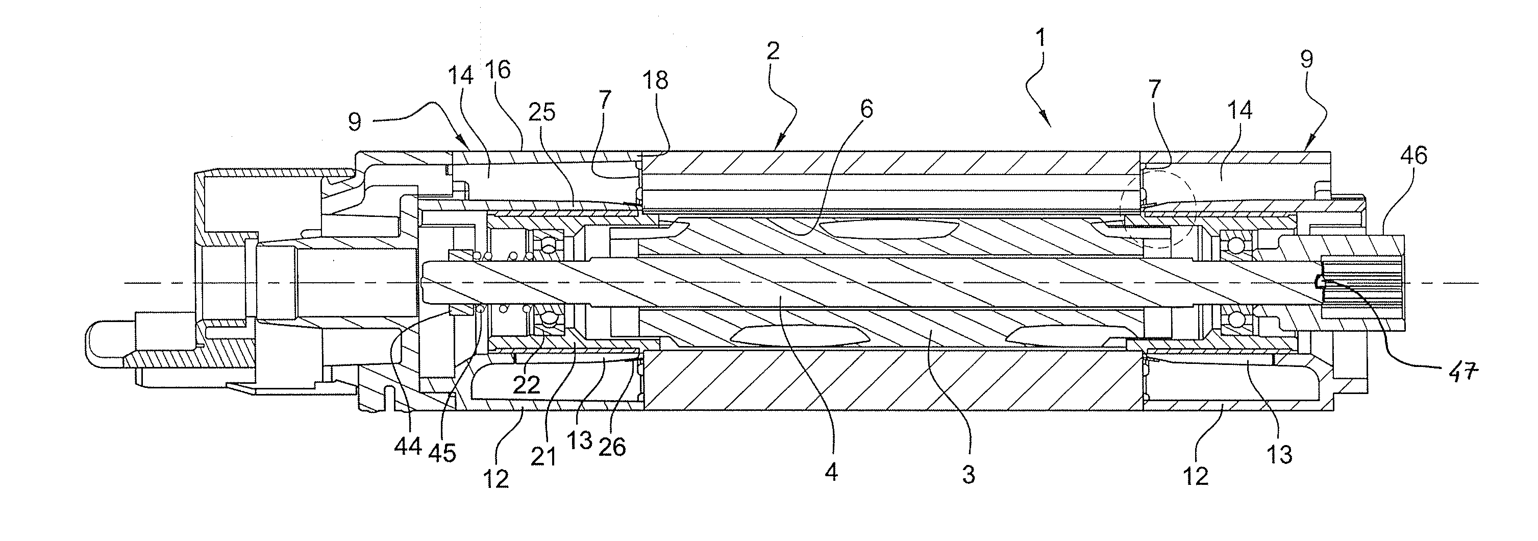
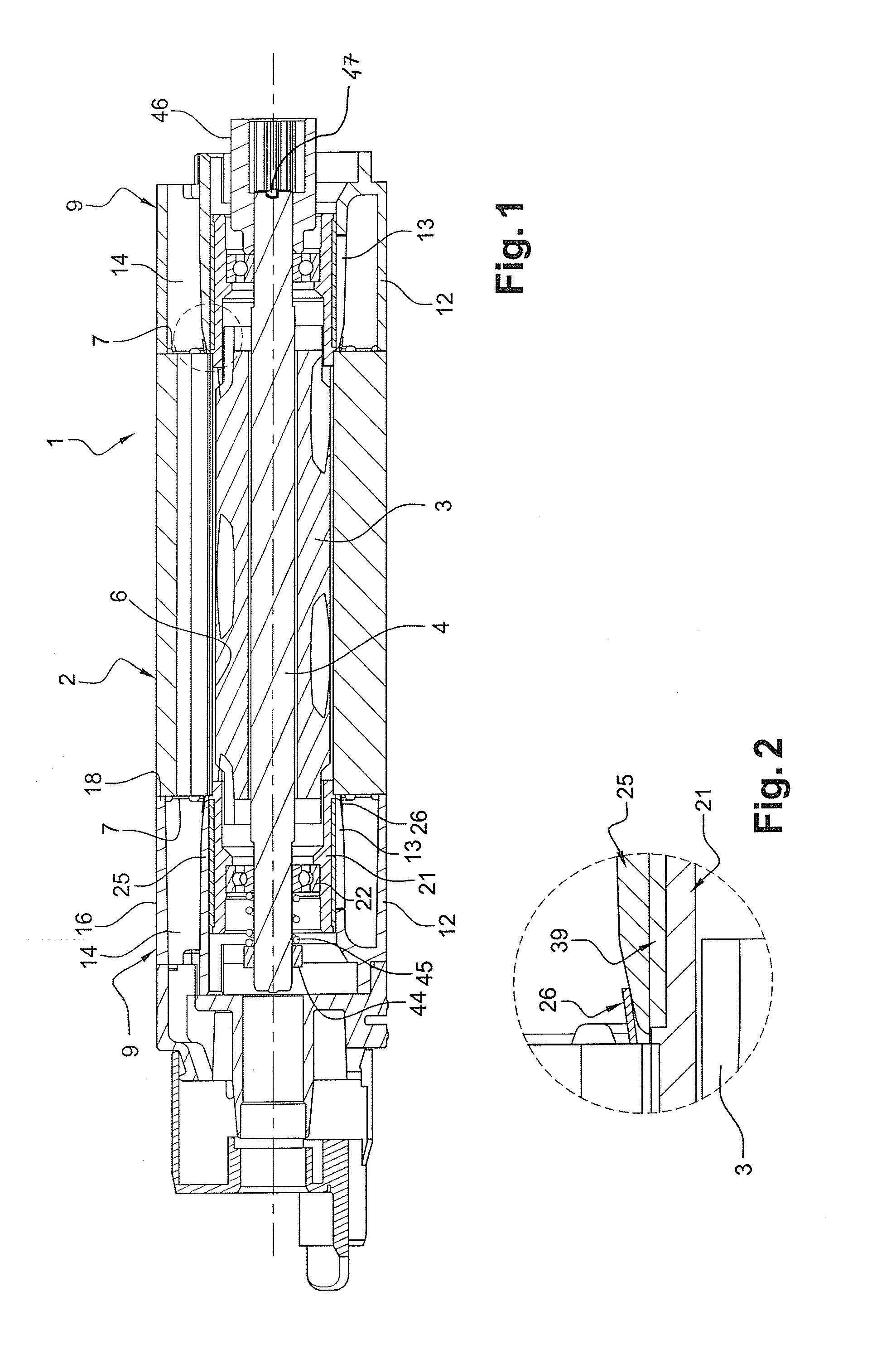
[0062]FIG. 1 shows an induction motor 1 according to a particular embodiment of the invention. The motor 1 can be a two-way rotation motor. It includes a stator 2 and a rotor assembly. The rotor assembly includes a rotor 3, for example a squirrel-cage rotor. The rotor 3 is fixed to a shaft 4.

[0063]The motor 1 is designed to be inserted in the hollow body of a substantially longitudinal actuator (not shown). Said actuator is intended to be fixed to a building, horizontally, and used in home automation applications, e.g. to roll up and down cloths, screens, blinds and roller shutters. Thus, the motor 1 is substantially tubular. In other words, the length of the stator 2 is generally greater than its outside diameter.

[0064]The stator 2 may include a bundle of plates forming a central bore 6. The rotor 3 is disposed within the central bore 6.

[0065]The stator 2 is centered in the hollow body of the longitudinal actuator.

[0066]The stator 2 comprises, on the circumference of its central bo...


PUM

PropertyMeasurementUnit
Shapeaaaaaaaaaa
aaaaaaaaaa

Abstract

Induction motor capable of being housed in a tubular actuator and method of assembling this motor. This motor (1) comprises: (i) a stator (2), (ii) a rotor assembly, (iii) a bowl (9) capable of protecting a bundle formed at one end (7) of the stator (2), the bowl (9) comprising an internal skirt (13), (iv) means of supporting the rotor assembly allowing the rotor assembly to rotate with respect to the stator (2), the support means comprising a bearing (21) positioned inside the internal skirt (13), the bearing (21) comprising a region that rests twice, axially and radially, against the stator (2).

Description

TECHNICAL FIELD[0001]The present invention relates to an induction motor, to be placed inside a tubular actuator for home automation applications to be used in particular to roll up and down cloths, blinds, screens, and roller shutters, and a method of assembling such a motor.BACKGROUND[0002]Induction motors typically include a stator having a bore within which a rotor is disposed. The stator comprises teeth distributed uniformly over its inner wall and separated by notches. The teeth support coils, which extend into the notches. The coils allow the establishment of a rotating magnetic field causing rotation of the rotor. The assembly of the coils forms the winding.[0003]It is desirable that the motors to be housed in actuators for home automation applications emit the least possible noise for user comfort. The noise originates from the vibrations inside the motor. The vibrations are generally caused by the clearances between the components of the motor, including rotor eccentricity...

Claims


Application Information

Patent Timeline
IPC IPC(8): H02K7/14H02K7/00
CPCH02K7/14H02K7/003H02K5/15H02K17/16Y10T29/49009
Inventor BRONDEX, ADRIENLANFROY, VINCENT
Owner SOMFY ACTIVITES SA
Why Eureka
Try Eureka