Induction motor capable of being housed in a tubular actuator and method of assembling this motor

a technology of induction motor and tubular actuator, which is applied in the direction of supporting/enclose/casing, mechanical energy handling, electrical equipment, etc., can solve the problems of motor malfunction, increase eccentricity, and increase the risk of rotor eccentricity, so as to limit the intensity of noise emitted during operation

Active Publication Date: 2017-12-05
SOMFY ACTIVITES SA
View PDF21 Cites 1 Cited by
  • Summary
  • Abstract
  • Description
  • Claims
  • Application Information

AI Technical Summary

Benefits of technology

[0010]Therefore, the present invention aims to overcome some or all of these drawbacks by providing an induction motor allowing immediate re-centering of the rotor in the stator bore to limit the intensity of the noise emitted during operation.
[0016]Thus, the induction motor according to the invention makes it possible, thanks to a dual axial and direct radial abutment between the bearing and the rotor, to reduce the tolerance stack-up between said elements and, as a consequence, clearances and associated vibrations. This results in a lower sound intensity in operation, for greater user comfort. In particular, the tolerance stack-up between the stator and the rotor comprises only the bearing stack-up, without any other intermediate element, the bearing alone providing the direct rotating contact between the rotor and stator.
[0020]The rolling is used to further reduce the noise, compared to the use of a bearing alone to ensure rotation of the rotor relative to the stator. In this case, the tolerance stack-up between the stator and the rotor comprises the tolerance stack-ups of the bearing and the rolling, without any other intermediate element.
[0022]This makes it possible to mount the rolling from the outside inwardly, i.e. in the direction of the stator.
[0028]This prevents the risks of electrical contact between the coil end and an electrically conductive element, which is likely to cause a short circuit leading to a motor breakdown.

Problems solved by technology

Their deterioration, during or after assembly, due in particular to the axial abutment of a component against the stator, may cause motor malfunction.
However, the presence of said protection element tends to move away the bearings used to ensure the rotation of the rotor.
It can therefore increase eccentricity.
However one has to keep in mind that the farther away the bearings are from the stator, the greater is the risk of rotor eccentricity.
Rotor eccentricity can cause vibrations and, as a consequence, noise, during operation.
This multitude of clearances in the tolerance stack-up contributes to the generation of vibrations during operation.
Such a distance may cause a problem of rotor eccentricity.
In operation, rotor eccentricity generates vibration and, as a result, noise.

Method used


Image

  • Induction motor capable of being housed in a tubular actuator and method of assembling this motor
  • Induction motor capable of being housed in a tubular actuator and method of assembling this motor
  • Induction motor capable of being housed in a tubular actuator and method of assembling this motor

Examples


Embodiment Construction

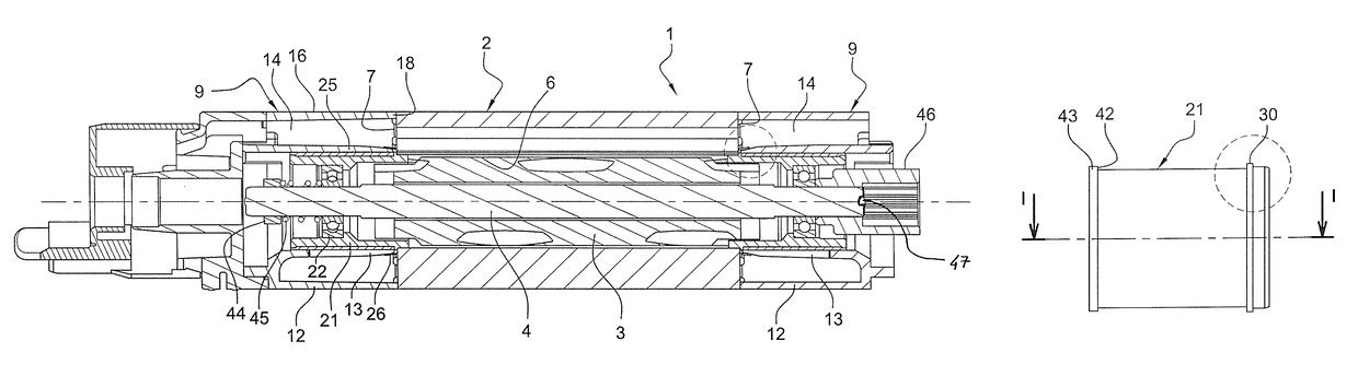
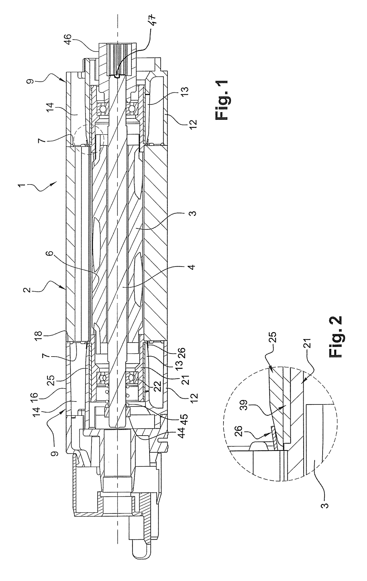
[0062]FIG. 1 shows an induction motor 1 according to a particular embodiment of the invention. The motor 1 can be a two-way rotation motor. It includes a stator 2 and a rotor assembly. The rotor assembly includes a rotor 3, for example a squirrel-cage rotor. The rotor 3 is fixed to a shaft 4.

[0063]The motor 1 is designed to be inserted in the hollow body of a substantially longitudinal actuator (not shown). Said actuator is intended to be fixed to a building, horizontally, and used in home automation applications, e.g. to roll up and down cloths, screens, blinds and roller shutters. Thus, the motor 1 is substantially tubular. In other words, the length of the stator 2 is generally greater than its outside diameter.

[0064]The stator 2 may include a bundle of plates forming a central bore 6. The rotor 3 is disposed within the central bore 6.

[0065]The stator 2 is centered in the hollow body of the longitudinal actuator.

[0066]The stator 2 comprises, on the circumference of its central bo...


PUM

PropertyMeasurementUnit
electrically insulatingaaaaaaaaaa
shapeaaaaaaaaaa
magnetic fieldaaaaaaaaaa

Abstract

Induction motor capable of being housed in a tubular actuator and method of assembling this motor. This motor (1) comprises: (i) a stator (2), (ii) a rotor assembly, (iii) a bowl (9) capable of protecting a bundle formed at one end (7) of the stator (2), the bowl (9) comprising an internal skirt (13), (iv) means of supporting the rotor assembly allowing the rotor assembly to rotate with respect to the stator (2), the support means comprising a bearing (21) positioned inside the internal skirt (13), the bearing (21) comprising a region that rests twice, axially and radially, against the stator (2).

Description

TECHNICAL FIELD[0001]The present invention relates to an induction motor, to be placed inside a tubular actuator for home automation applications to be used in particular to roll up and down cloths, blinds, screens, and roller shutters, and a method of assembling such a motor.BACKGROUND[0002]Induction motors typically include a stator having a bore within which a rotor is disposed. The stator comprises teeth distributed uniformly over its inner wall and separated by notches. The teeth support coils, which extend into the notches. The coils allow the establishment of a rotating magnetic field causing rotation of the rotor. The assembly of the coils forms the winding.[0003]It is desirable that the motors to be housed in actuators for home automation applications emit the least possible noise for user comfort. The noise originates from the vibrations inside the motor. The vibrations are generally caused by the clearances between the components of the motor, including rotor eccentricity...

Claims


Application Information

Patent Timeline
Patent Type & Authority Patents(United States)
IPC IPC(8): H02K7/14H02K7/00H02K5/15H02K17/16
CPCH02K7/14H02K5/15H02K7/003Y10T29/49009H02K17/16
Inventor BRONDEX, ADRIENLANFROY, VINCENT
Owner SOMFY ACTIVITES SA
Why Eureka
Try Eureka