
RFID antenna

A technology of antennas and traces, applied in the field of antennas that can be obtained by means of the method, capable of solving problems such as limited space

Inactive Publication Date: 2018-10-23
LINXENS HLDG SAS
View PDF6 Cites 0 Cited by
  • Summary
  • Abstract
  • Description
  • Claims
  • Application Information

AI Technical Summary

Problems solved by technology

Thickness issues are particularly important when intending to package antennas in mobile phones, especially new generation thin smartphones, where space is quite constrained

Method used


Image

  • RFID antenna
  • RFID antenna
  • RFID antenna

Examples


Embodiment Construction

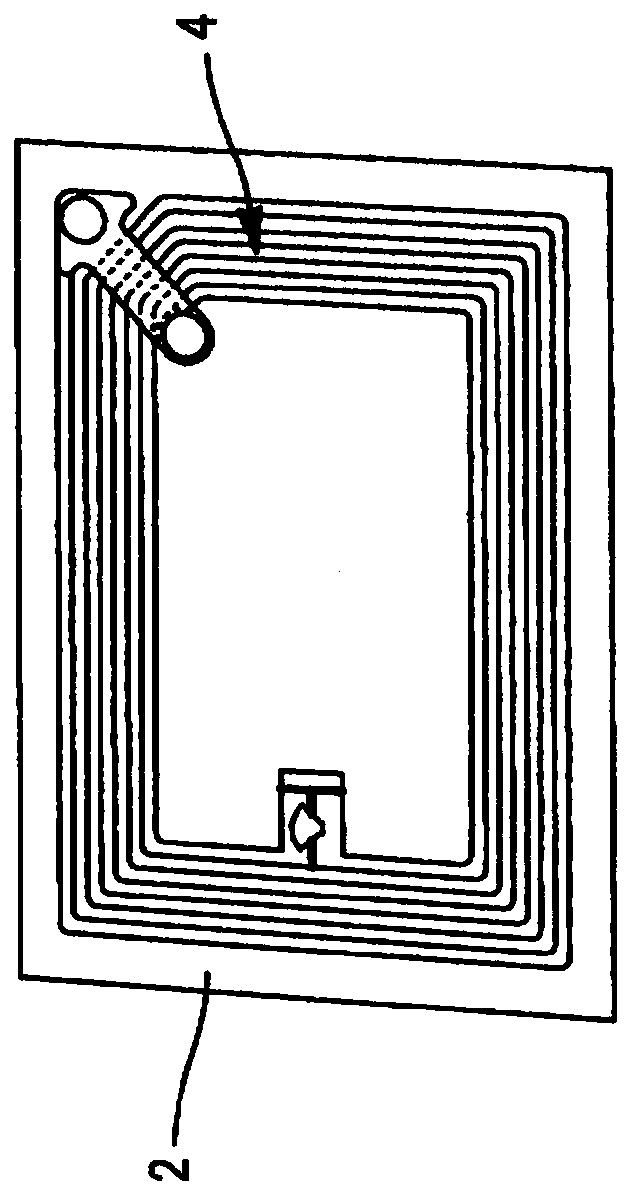
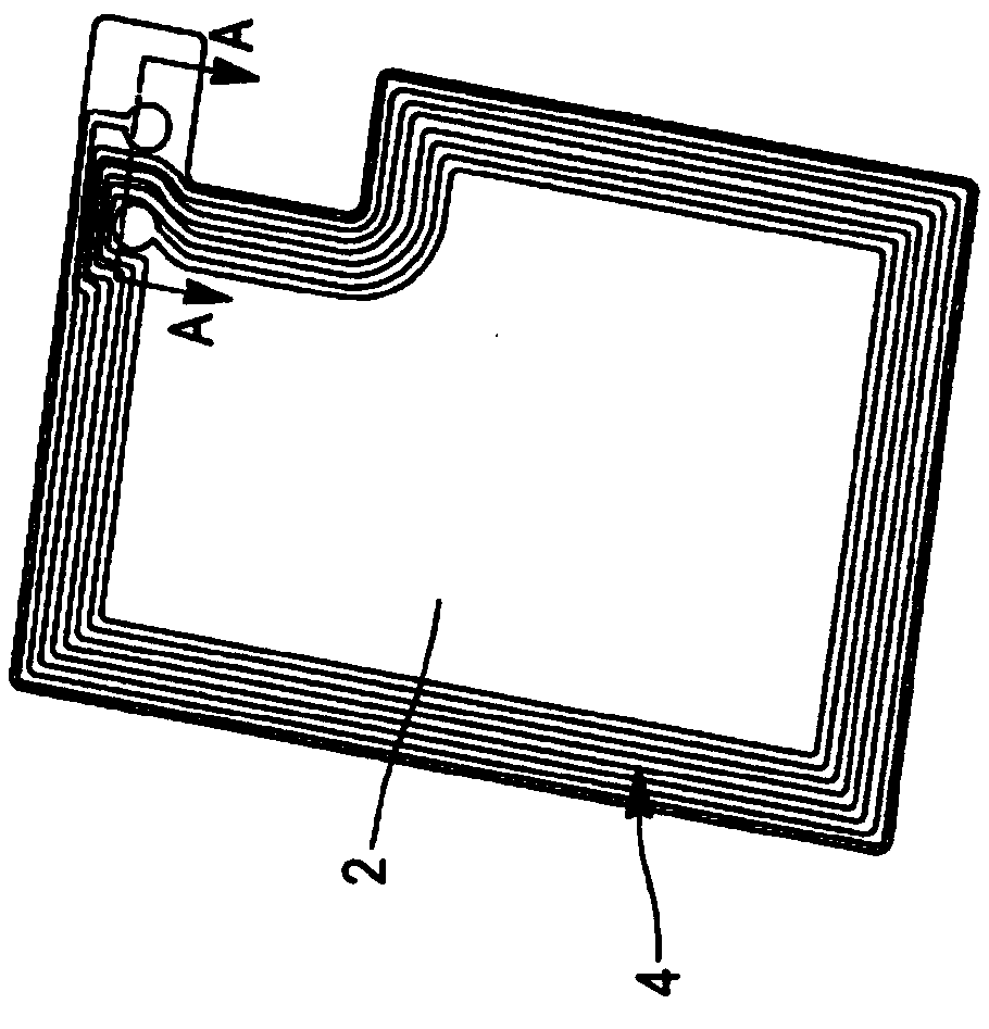
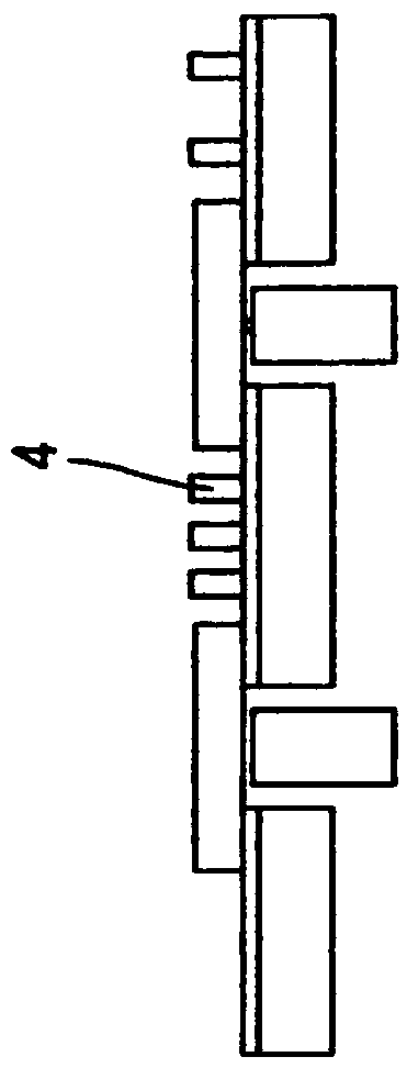
[0018] figure 1 A first embodiment of a planar RFID antenna is shown comprising a support substrate 2 on which conductive traces 4 have been formed. In the context of the present invention, the substrate 2 is made of a magnetically flexible sheet comprising magnetic particles (such as powder or flakes of magnetic ferrite) dispersed in a resin binder. An example of such a ferritic sheet is Liqualloy™ flexible film sold by Alps Electric Ltd. Ferritic sheets of this type are also readily available through ferritic material suppliers such as Japanese ferritic material suppliers.

[0019] The conductive traces have been formed directly on the first major surface of the ferrite sheet such that the conductive traces extend in a plane parallel to the first major surface. The conductive traces are for example made of copper. Such as figure 1 As shown, the antenna trace comprises a plurality of turns (here there are four turns) in the form of a helix. The outer bend comprises a co...


PUM


Abstract

The present invention relates to a method for manufacturing an antenna, and the method comprises the steps: providing a magnetic sheet made of a composite material comprising magnetic particles and asynthetic resin, the magnetic sheet having a first surface; directly forming a conductive planar trace with at least one bent part on the first surface of the magnetic sheet.

Description

[0001] This application is a divisional application of an invention patent application with an application date of September 11, 2012, an application number of 201280045015.9, and an invention title of "Radio Frequency Identification Antenna". technical field [0002] The invention relates to a method for manufacturing an antenna and to an antenna obtainable by means of said method. Background technique [0003] The use of tags with radio frequency identification (RFID) antennas to identify and monitor objects is well known in the art. Such tags include, for example, an antenna loop formed by conductive traces electrically connected to an integrated circuit (IC) chip including a memory. The tags use electromagnetic fields generated by RFID readers. With such a tag in the electromagnetic field for a long enough time, the RFID antenna will be energized and the electronic circuit can send a signal towards the reader or a separate receiving antenna. [0004] Such modes for con...

Claims


Application Information

Patent Timeline
Patent Type & Authority Applications(China)
IPC IPC(8): H01Q1/38H01Q7/06H01Q1/22H01Q7/00
CPCH01Q1/2225H01Q1/38H01Q7/00H01Q7/06
Inventor C·马蒂厄Y·W·耶普
Owner LINXENS HLDG SAS
Learn More