

Grouser shoe and fabrication method
a manufacturing method and grouser technology, applied in the field of grouser shoes, can solve the problems of limited design variations by the described manufacturing method, relatively little has been achieved in recent years in the direction of breakthrough construction techniques or fundamental design changes, and the service life of grouser shoes is subject to wear, etc., to achieve comfortable operating environment for operators, increase the service life of grouser shoes, and increase the control of the operator of the devi
- Summary
- Abstract
- Description
- Claims
- Application Information
AI Technical Summary
Benefits of technology
Problems solved by technology
Method used
Image

Examples
Embodiment Construction
[0024] The invention of this application relates to an improved grouser shoe of a unique configuration together with a method of manufacture thereof.
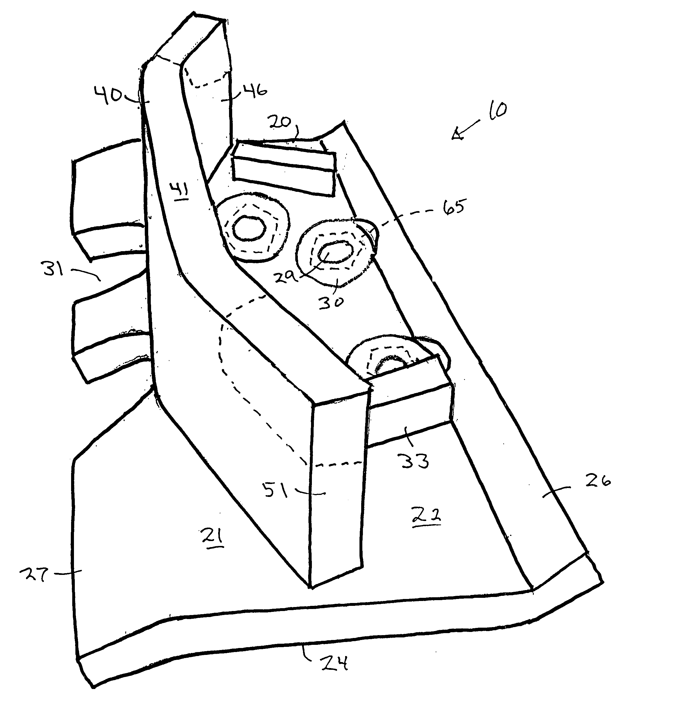
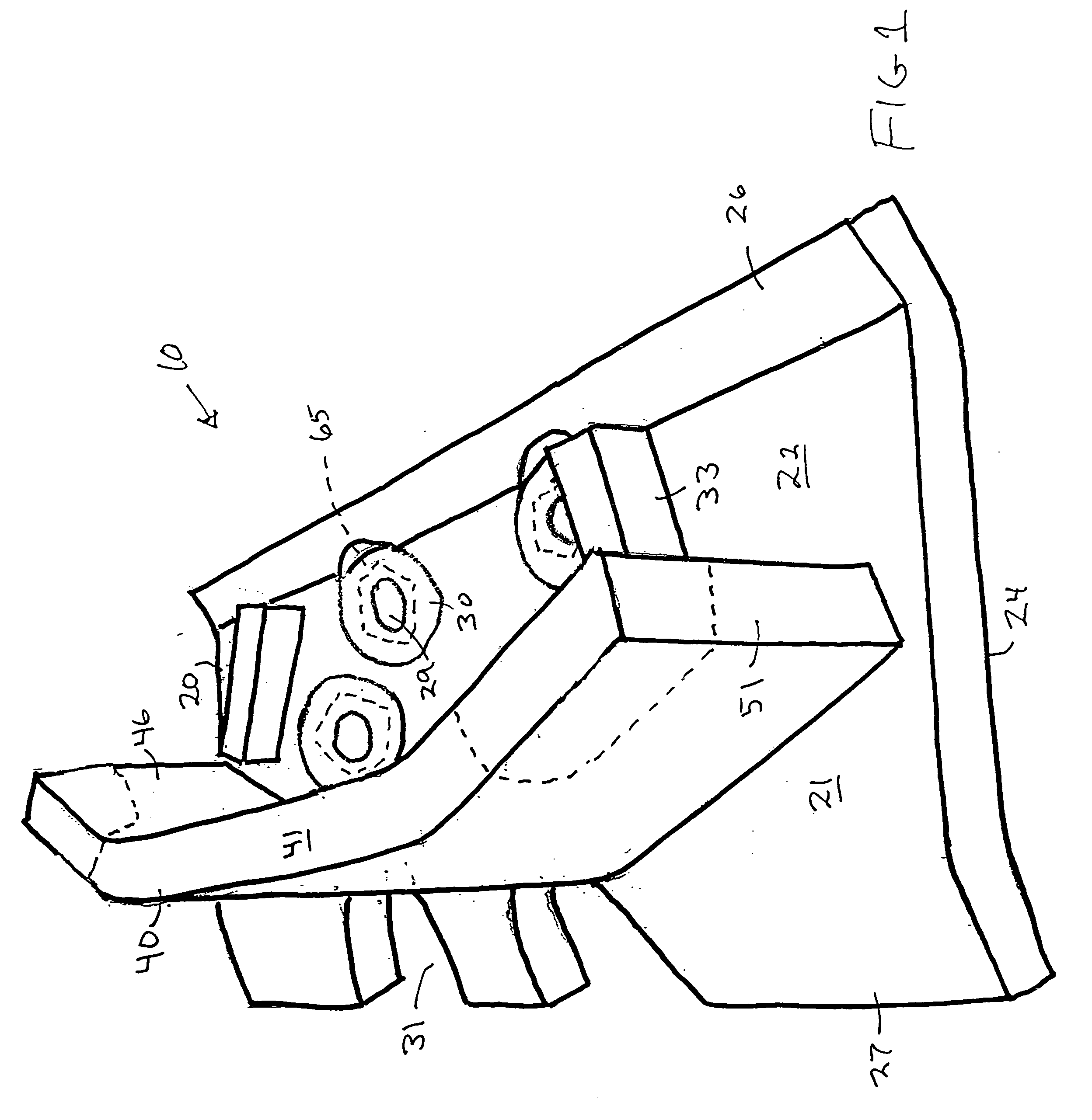
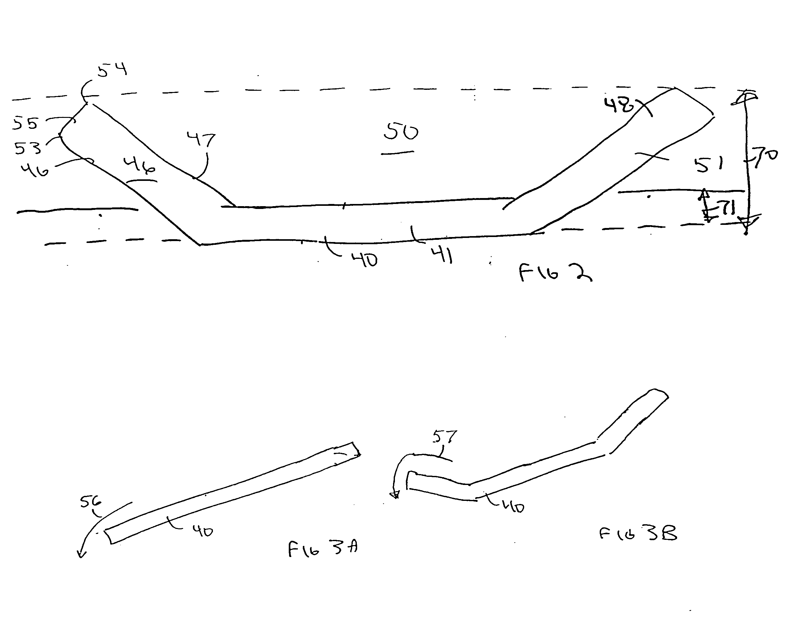
[0025] The present invention relates to a grouser shoe 10 which has a pad 20 and a bar 40 (FIG. 1).
[0026] The shoe itself is for engaging the ground in order to provide the support and drive for a tracked vehicle. Typically this tracked vehicle is a bulldozer or a heavy loader, although it is suitable for use with other forms of tracked vehicles.
[0027] The size, shape, and configuration of the shoe is selected in view of the particular tracked vehicle with which the shoe is to be utilized. This will differ from device to device as well as manufacturer to manufacturer. The present shoe is to be utilized with a tracked vehicle having a sprocket-type drive mechanism through an intermediate integral drivelink with additional location / flotation rollers (not shown). The sprocket drive can be a three point with one high sprocket and two idl...
PUM
| Property | Measurement | Unit |
|---|---|---|
| Rockwell hardness | aaaaa | aaaaa |
| angle | aaaaa | aaaaa |
| Rockwell hardness | aaaaa | aaaaa |
Abstract
Description
Claims
Application Information