Liquid crystal display device with improved viewing angle characteristics

a liquid crystal display and viewing angle technology, applied in the direction of counting mechanisms/objects, instruments, computing, etc., to achieve the effect of improving the viewing angle characteristics and broad viewing angle characteristics

Active Publication Date: 2005-11-17
AU OPTRONICS CORP
View PDF12 Cites 142 Cited by
  • Summary
  • Abstract
  • Description
  • Claims
  • Application Information

AI Technical Summary

Benefits of technology

[0015] An MVA type liquid crystal display device has broad viewing angle characteristics, and by restricting the liquid crystal molecule alignment direction to a plurality of directions, averages the bias in viewing angles and so improves the view

Problems solved by technology

Even in MVA type liquid crystal display panels in which the liquid crystal alignment direction is r

Method used


Image

  • Liquid crystal display device with improved viewing angle characteristics
  • Liquid crystal display device with improved viewing angle characteristics
  • Liquid crystal display device with improved viewing angle characteristics

Examples


first embodiment

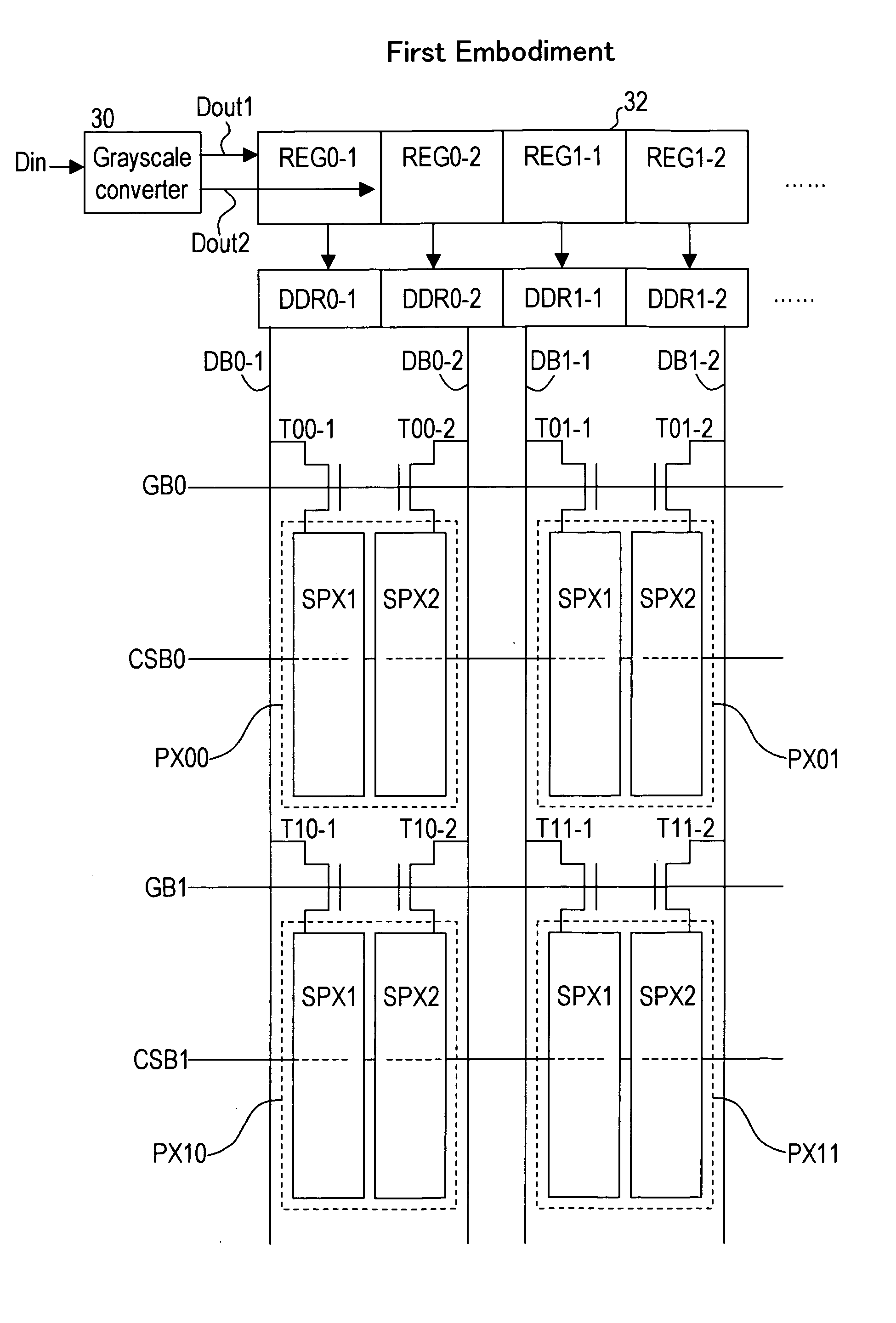
[0099]FIG. 10 is a view of a liquid crystal display device in a first embodiment. In this embodiment, a plurality of subpixel electrodes, for example first and second subpixel electrodes SPX1, SPX2, are provided in each of the pixels PX00, PX01, PX10, PX11 arranged in a matrix in the MVA type liquid crystal display panel. Thin film transistors Tij-1, Tij-2 (ij=00, 01, 10, 11) are provided, as switching means, to the first and second subpixel electrodes SPX1, SPX2. Also, a pair of data bus lines DB0-1, DB0-2 are provided, to which the thin film transistors T00-1, T10-1 and T00-2, T10-2 respectively of the pixels PX00, PX10 arranged in the vertical direction in the first column are connected; and a pair of data bus lines DB1-1, DB1-2 are provided, to which the thin film transistors T01-1, T11-1 and T01-2, T11-2 respectively of the pixels PX01, PX11 arranged in the vertical direction in the second column are connected. These pairs of data bus lines DB0-1, DB0-2 and DB1-1, DB1-2 are dri...

second embodiment

[0134]FIG. 25 shows the relation between input grayscale and luminance in the liquid crystal display device of a second embodiment. The configuration of the liquid crystal display panel of the second embodiment is similar to that of the first embodiment; pixel electrodes are divided into a plurality of subpixel electrodes, to each of which a data voltage is applied corresponding to an output grayscale signal resulting from grayscale conversion of an input grayscale signal. In the first embodiment, the first subpixel electrode was made small, and the second subpixel electrode was made large. That is, the area ratio of the first and second subpixel electrodes was made 1:2, 1:3, or similar. In this case, a voltage was applied to the first subpixel electrode corresponding to a first output grayscale signal Dout1 which rises to the maximum grayscale value from the minimum grayscale value in the low grayscale region of the input grayscale signal, while a second output grayscale signal Dou...

third embodiment

[0145]FIG. 31 is a schematic diagram showing an example of the configuration of subpixel electrodes in a third embodiment. In this example, each pixel is divided into a first and second subpixel electrode SPX1, SPX2, and combinations of area ratios of 1:2 and 1:3 are intermixed. That is, in the row direction, pixels PXa with an area ratio of 1:3 and pixels PXb with an area ratio of 1:2 are arranged in alternation. In this case, two data bus lines may be provided for each column, and there may be two gate bus lines in each row for one data line per column.

[0146] As shown in the luminance characteristic diagram of FIG. 18 in the first embodiment, when a high-luminance output grayscale signal which rises to the maximum grayscale value in a low-input grayscale region is applied to the small-area first subpixel electrode, and a low-luminance output grayscale signal which rises from the minimum grayscale value in a high-input grayscale region is applied to the large-area second subpixel ...


PUM


Abstract

A liquid crystal display device, in which the liquid crystal molecules are aligned vertically when no voltage is applied, includes pixels each having plural sub-pixel electrodes, a data bus drive circuit for applying drive signals to the sub-pixel electrodes via a data bus line and a switching element, and alignment regulation structure for regulating the direction of alignment of liquid crystal molecules. The first and second sub-pixel electrodes have different areas. The data bus drive circuit applies a first drive signal, which causes luminance to change from minimum to maximum for an increase of input grayscale of image signal, to the first sub-pixel electrode, and a second drive signal, which causes the luminance to be lower than the first drive signal, to the second sub-pixel electrode.

Description

CROSS-REFERENCE TO RELATED APPLICATIONS [0001] This application is based upon and claims the benefit of priority from the prior Japanese Patent Application No. 2004-134954, filed on Apr. 30, 2004, the entire contents of which are incorporated herein by reference. BACKGROUND OF THE INVENTION [0002] 1. Field of the Invention [0003] This invention relates to a perpendicular-alignment type liquid crystal display device, and in particular to a liquid crystal display device in which viewing angle characteristics are improved, so that degradation of color reproduction of an image when viewed at an oblique angle with respect to the display screen is alleviated. [0004] 2. Description of the Related Art [0005] Liquid crystal display devices can be classified into various display modes according to how the liquid crystal material is controlled when displaying text and images. For example, a twisted-nematic (TN) liquid crystal type is a display type utilizing nematic liquid crystals with a liqu...

Claims


Application Information

Patent Timeline
IPC IPC(8): G02F1/133G02F1/139G02F1/1337G02F1/1343G02F1/1368G09G3/20G09G3/36
CPCG02F1/133753G02F2001/133742G02F2001/134345G09G3/2074G09G2320/0285G09G3/3607G09G3/3648G09G2320/0276G09G2320/028G09G3/2077G09G2300/0447G02F1/133742G02F1/134345G06M11/00G06M1/107G06M1/024
Inventor KAMADA, TSUYOSHITAKEDA, ARIHIRO
Owner AU OPTRONICS CORP
Why Eureka
Try Eureka