Lens holding jig

a technology of holding jigs and lenses, applied in the field of lens holding jigs, can solve problems such as flow irregularities, and achieve the effect of reducing the occurrence of lens appearance defects

Inactive Publication Date: 2005-11-17
HOYA LENS MFG PHILIPPINES
View PDF3 Cites 24 Cited by
  • Summary
  • Abstract
  • Description
  • Claims
  • Application Information

AI Technical Summary

Benefits of technology

[0019] The inventor has made intensive studies to achieve the first object, and has found that the occurrence of a lens appearance defect can be reduced as much as possible by providing side holders for supporting left and right edges of a lens, each of the side holders hav

Problems solved by technology

Flow irregularities are also produced when a film of hard coating solution formed between the lens and the side holder bursts because the

Method used


Image

  • Lens holding jig
  • Lens holding jig
  • Lens holding jig

Examples


Embodiment Construction

[0039] Embodiments of lens holding jigs according to the present invention will be described below. However, the present invention is not limited to the embodiments described below.

[0040] A lens holding jig according to the present invention is used in a dipping process for forming a hard coating or the like on a lens having a thin edge or a lens having a sharp edge.

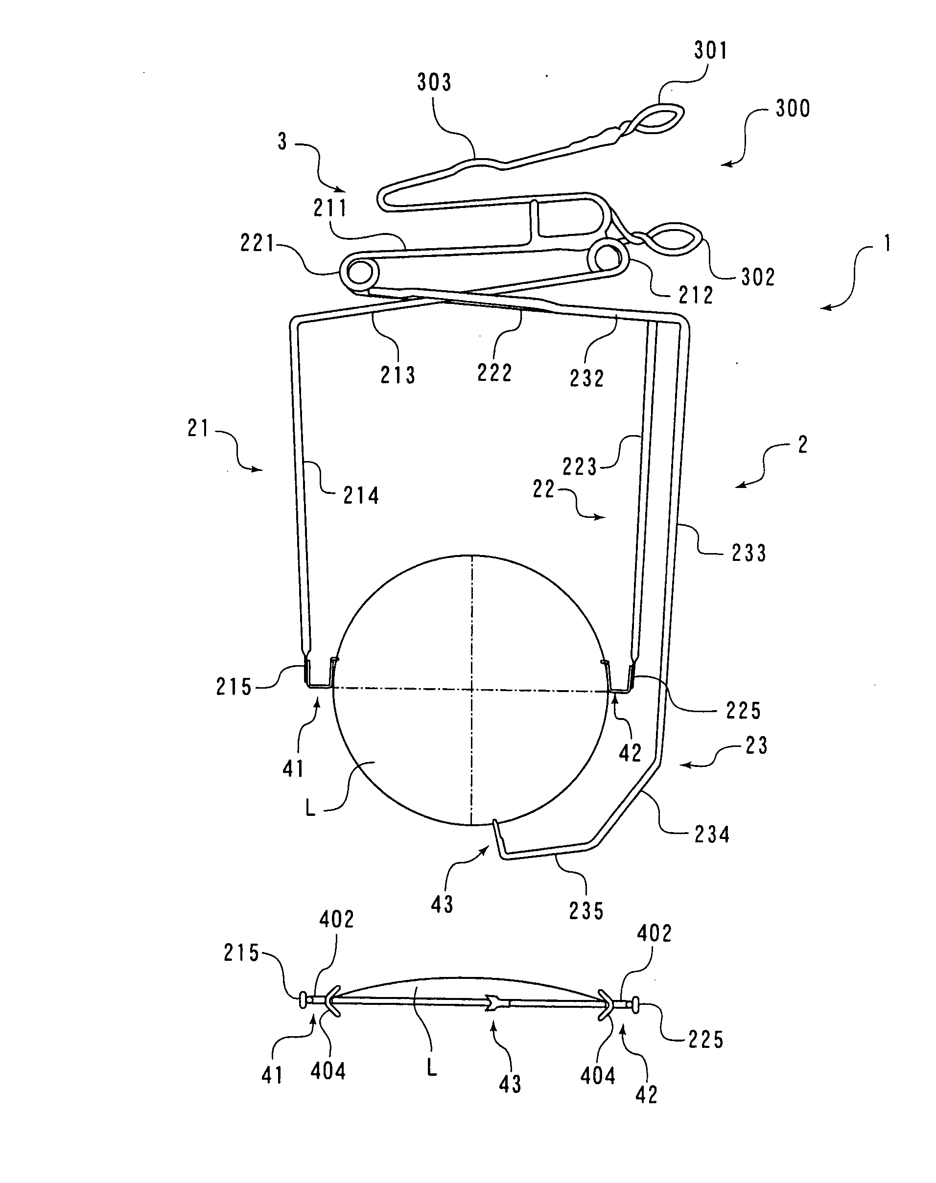
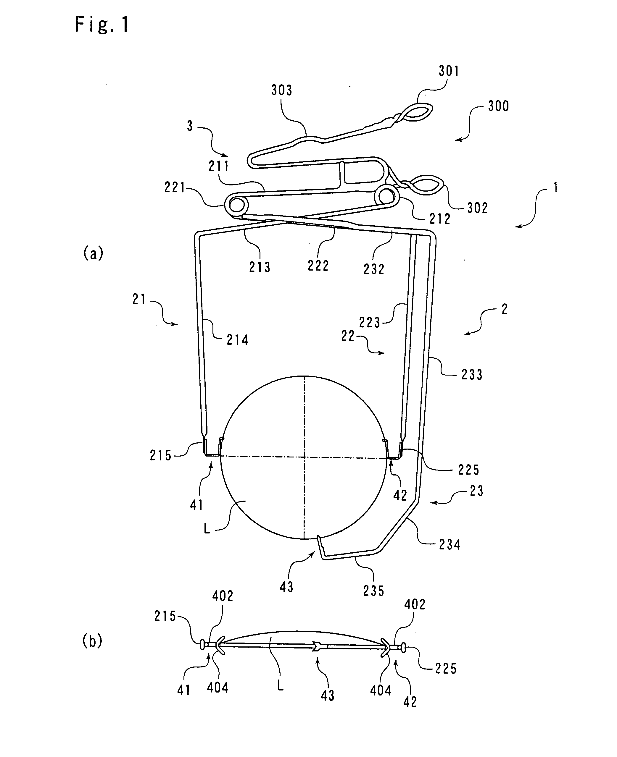
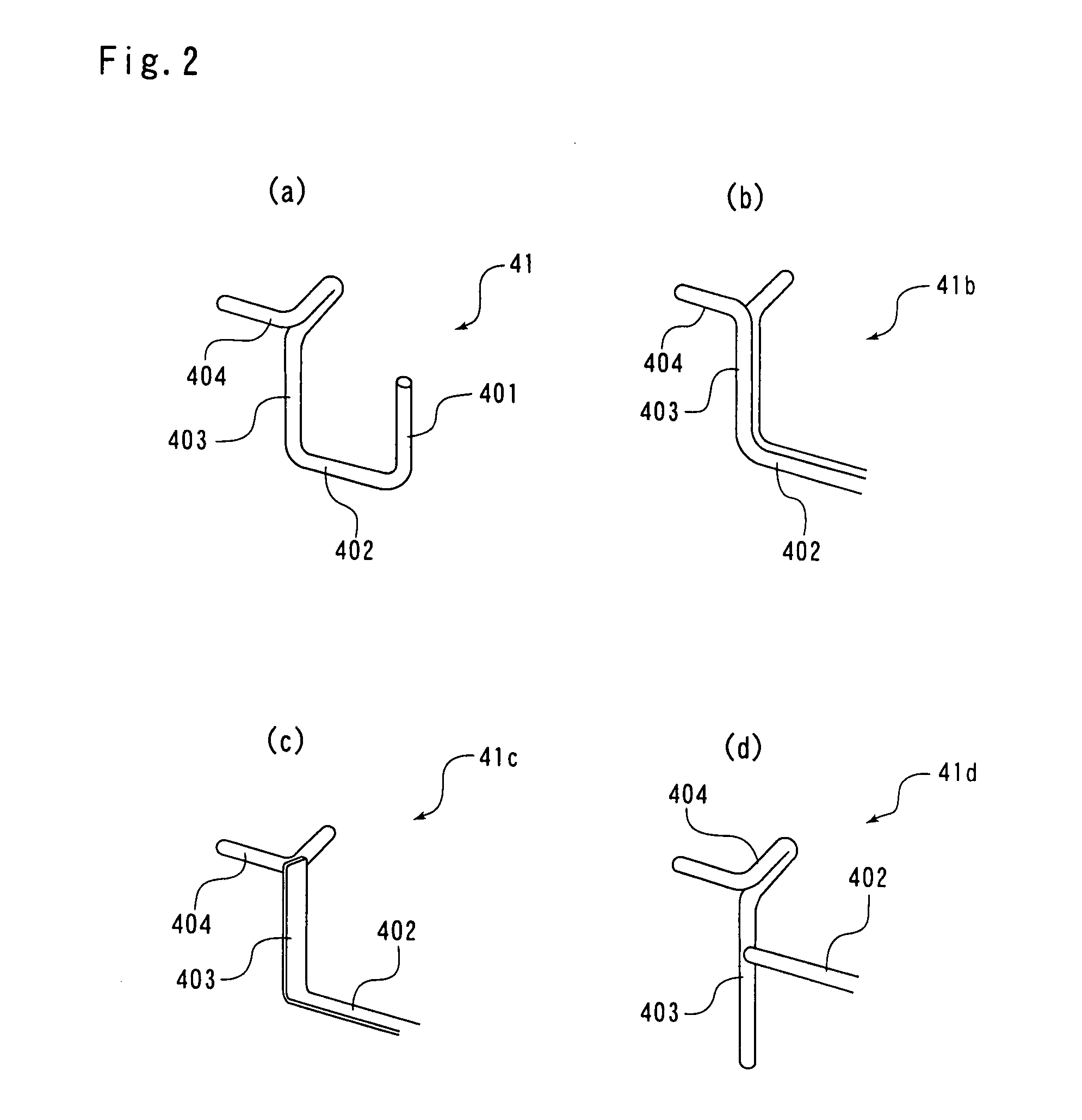
[0041] An embodiment of a lens holding jig according to a first invention, which has improved side holders, will be described below with reference to FIGS. 1(a) through 4(d). The lens holding jig is applied as a single lens holding jig.

[0042] FIGS. 1(a) and 1(b) show a lens holding jig according to the present invention which is holding a lens with its edge disposed vertically, i.e., which is holding a lens vertically: FIG. 1(a) is a front elevational view of the lens holding jig and FIG. 1(b) is a view showing a lens held by left and right side holders of the lens holding jig.

[0043] The lens holding jig 1 is made of...


PUM

PropertyMeasurementUnit
Angleaaaaaaaaaa

Abstract

A lens holding jig used for immersing a lens (L) in a liquid by holding the lens (L) at at least three positions that are side holding portions (41, 42) for holding both left and right edges of the lens (L), and at a lower-side holding portion (43) for holding the lower edge of the lens (L). The jig is structured such that the side holding portions (41, 42) each have a letter V-shaped holding portion (404) for holding the edge of the lens and have a vertically extending portion (403) extending downward from the V-shaped holding portion (404) along the edge of the lens (L). Further, a lower-side holding portion (1) is structured so as to have a support plate (11) having at its upper end a cut-out portion (110) for supporting an end edge of a lens (L2), and an auxiliary plate (12) formed in one piece with the support plate (11) at an intersection angle. The jig can reduce as much as possible the occurrence of appearance defect of a lens at the side holding portions for supporting the sides of a lens and at the lower-side holding portion for supporting the lower side of the lens.

Description

TECHNICAL FIELD [0001] The present invention relates to a lens holding jig. More particularly, the present invention relates to a lens holding jig for use in dipping a lens in a treating solution such as a hard coating solution or the like. BACKGROUND ART [0002] Since plastic spectacle lenses are easily scratched, it is customary practice to coat them with an abrasion-resistant hard coating. Generally, a lens is coated with a hard coating by applying a hard coating solution to the lens surfaces of the lens and then drying the applied hard coating solution into a hard layer. [0003] Processes of applying a hard coating to a lens include a spin-coating process and a dipping process. The dipping process is mainly relied upon for its higher productivity. [0004] According to the conventional dipping process, lenses are mounted on a lens holding jig which is designed to hold about 30 lenses simultaneously, and then the lenses are dipped, together with the lens holding jig, in a hard coatin...

Claims


Application Information

Patent Timeline
IPC IPC(8): B05C3/09G02C7/00B05C3/10B05C13/02B29D11/00B65G49/02
CPCB05C3/09B29D11/00903B05C13/02B29D11/00432B29D11/00009
Inventor SHIMIZU, HIROSHI
Owner HOYA LENS MFG PHILIPPINES
Why Eureka
Try Eureka