Image processing apparatus and method, and program

a technology of image processing and output image, applied in the field of image processing apparatus, can solve the problems of artifact generation, low contrast, and high contrast, and achieve the effect of suppressing shortage or excess contrast of output image and suppressing artifacts in dynamic range compression

Inactive Publication Date: 2005-11-17
CANON KK
View PDF20 Cites 22 Cited by
  • Summary
  • Abstract
  • Description
  • Claims
  • Application Information

AI Technical Summary

Benefits of technology

[0015] The present invention has been made to solve the above-described problems, and has as its object to provide an image processing apparatus which can suppress shortage or excess of contrast of an output image and also suppress artifacts in dynamic range compression by generating an LUT to be used for dynamic range change in accordance with the feature amount of an image, and a method and program therefor.

Problems solved by technology

In the method described in reference 1, however, when the dynamic range of the image is compressed excessively, the contrast may be too low.
Conversely, when the dynamic range is expanded excessively, the contrast may be too high.
However, since the low- and high-frequency components are unbalanced, artifacts are generated by overshoot or undershoot.
That is, artifacts are generated when a low frequency is assigned to a narrow dynamic range in spite of a large information amount as an edge.

Method used


Image

  • Image processing apparatus and method, and program
  • Image processing apparatus and method, and program
  • Image processing apparatus and method, and program

Examples


Embodiment Construction

[0061] A preferred embodiment of the present invention will be described in detail in accordance with the accompanying drawings.

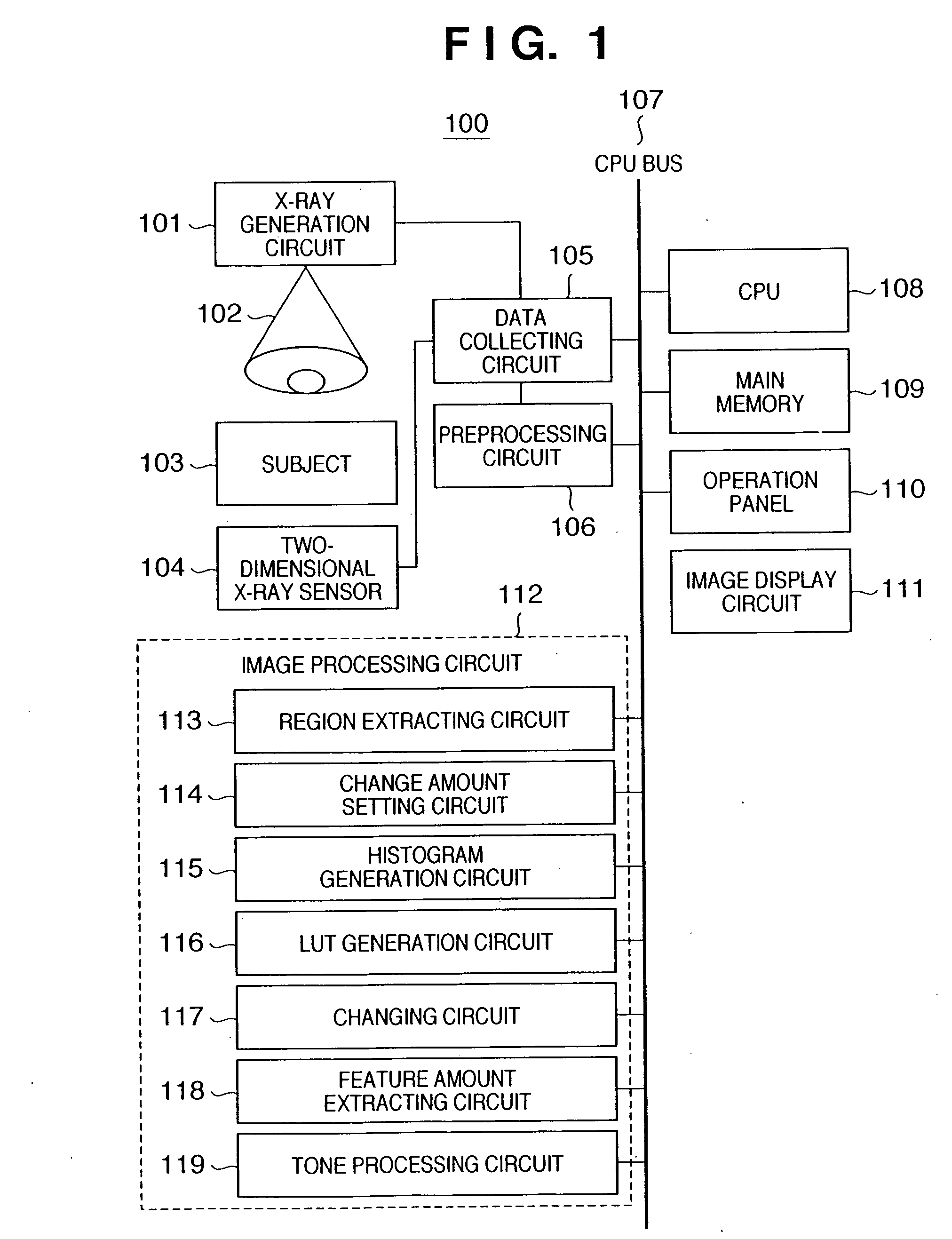
[0062]FIG. 1 is a block diagram showing the arrangement of an X-ray imaging device according to this embodiment.

[0063] An X-ray imaging device 100 shown in FIG. 1 has a function of executing effective image processing in outputting a radiographed image onto a film or monitor. The X-ray imaging device 100 comprises a data collecting circuit 105, preprocessing circuit 106, CPU 108, main memory 109, operation panel 110, image display circuit 111, and image processing circuit 112. These components are connected through a CPU bus 107 so that data can be transferred between them.

[0064] In the X-ray imaging device 100, the data collecting circuit 105 and preprocessing circuit 106 are connected to each other. A two-dimensional X-ray sensor 104 and X-ray generation circuit 101 are connected to the data collecting circuit 105.

[0065] The image processing circuit 1...


PUM


Abstract

A histogram is generated on the basis of the pixel value of an image. An LUT used for changing the dynamic range of the image is generated on the basis of the histogram value in each pixel value interval of the generated histogram. The dynamic range of the image is changed on the basis of the generated LUT.

Description

FIELD OF THE INVENTION [0001] The present invention relates to an image processing apparatus which changes the dynamic range of an image, and a method and program therefor. BACKGROUND OF THE INVENTION [0002] As the digital technology progresses recently, people convert a radiographic image into a digital image signal (the value of a pixel contained in the digital image signal will be referred to as a pixel value), execute image processing for the digital image signal, and display the image on a display device such as a CRT or output the image to a film. [0003] When a radiographic image is sensed, generally, tone conversion processing is executed by using a linear LUT or an LUT with an S-shaped tone conversion curve representing the characteristic of a film to make the converted digital image signal suitable for display or film output. [0004] In X-ray images of human bodies, the dynamic range of the subject changes depending on the individual difference between subjects or radiograph...

Claims


Application Information

Patent Timeline
Patent Type & Authority Applications(United States)
IPC IPC(8): A61B6/00G06K9/00G06T5/40H04N5/325
CPCG06T5/009G06T2207/10116G06T5/40
Inventor TAKAHASHI, NAOTO
Owner CANON KK
Why Eureka
Try Eureka