Optical fiber component, optical waveguide module, and manufacturing method

a manufacturing method and optical fiber technology, applied in the field of optical fiber components, can solve problems such as decreasing alignment precision, and achieve the effects of simplifying the manufacturing process, increasing alignment precision and optical fiber strength, and increasing optical fiber alignment precision

Inactive Publication Date: 2005-11-17
NEC CORP
View PDF10 Cites 33 Cited by
  • Summary
  • Abstract
  • Description
  • Claims
  • Application Information

AI Technical Summary

Benefits of technology

[0035] The optical fiber component according to the present invention comprises the housing block on which grooves are formed, optical fibers housed in the grooves, and the plane created in such a way that the end faces of the optical fibers and the end face of the housing block are in approximately the same plane. When the optical fibers and the optical waveguides are connected, this configuration causes the grooves to suppress the oscillation of the end faces of the optical fibers for increasing the alignment precision and the optical fiber strength. Fixing only a part of the optical fibers in the grooves with an adhesive avoids a condition, in which an adhesive running over from the grooves prevents the optical fiber component from being properly installed in the guiding grooves on the optical waveguide substrate, which would occur when the whole part of the optical fibers is fixed in the grooves with an adhesive. In addition, the holding block provided in the adhesive-fixing area works with the holding block to hold the optical fibers more firmly. By forming the groove as V-shaped, the V-grooves also increase the optical fiber alignment precision because each optical fiber is stabilized in the deepest position in the groove.
[0036] The optical waveguide module according to the present invention has the guiding grooves on the optical waveguide substrate on which the optical waveguides are formed. This configuration eliminates the need for the step of adhering the optical waveguide substrate to the V-groove substrate using the alignment marks, thus simplifying the manufacturing process and increasing the alignment precision. The optical fibers are held between the fixed grooves of the housing block and the guiding grooves of the optical waveguide substrate, and the end faces of the optical fibers and the end faces of the optical waveguides are joined and fixed. This causes the grooves to suppress the oscillation of the optical fibers in the guiding grooves during the manufacturing process, increases the alignment precision, suppresses the damages of the optical fibers, and increases the process yield.
[0037] The optical fiber component according to the present invention comprises a housing block having grooves on its surface and optical fibers housed in the grooves, wherein the end faces of the optical fibers and the end face of the housing block are in approximately the same plane and the side of the optical fibers that are housed in the grooves but do not face the grooves is exposed. When the optical fibers are connected to the optical waveguides, the grooves suppress the oscillation of the end faces of the optical fibers and, therefore, the alignment precision, as well as the optical fiber strength, is increased.

Problems solved by technology

On the other hand, when the whole part of the optical fibers is fixed in the grooves with an adhesive, the adhesive overflowed from the grooves solidifies and prevents the optical fiber component from being installed properly in the guiding grooves of the optical waveguide substrate, sometimes decreasing the alignment precision.

Method used


Image

  • Optical fiber component, optical waveguide module, and manufacturing method
  • Optical fiber component, optical waveguide module, and manufacturing method
  • Optical fiber component, optical waveguide module, and manufacturing method

Examples


first embodiment

[0053]FIG. 4 and FIG. 5 show an optical fiber array according to the present invention. FIG. 4 [1] is a top view, FIG. 4[2] is a front view, and FIG. 5 is a right side view. Although an optical fiber array is used as an optical fiber component in the embodiments of the present invention given below, the optical fiber component is not limited to an optical fiber array.

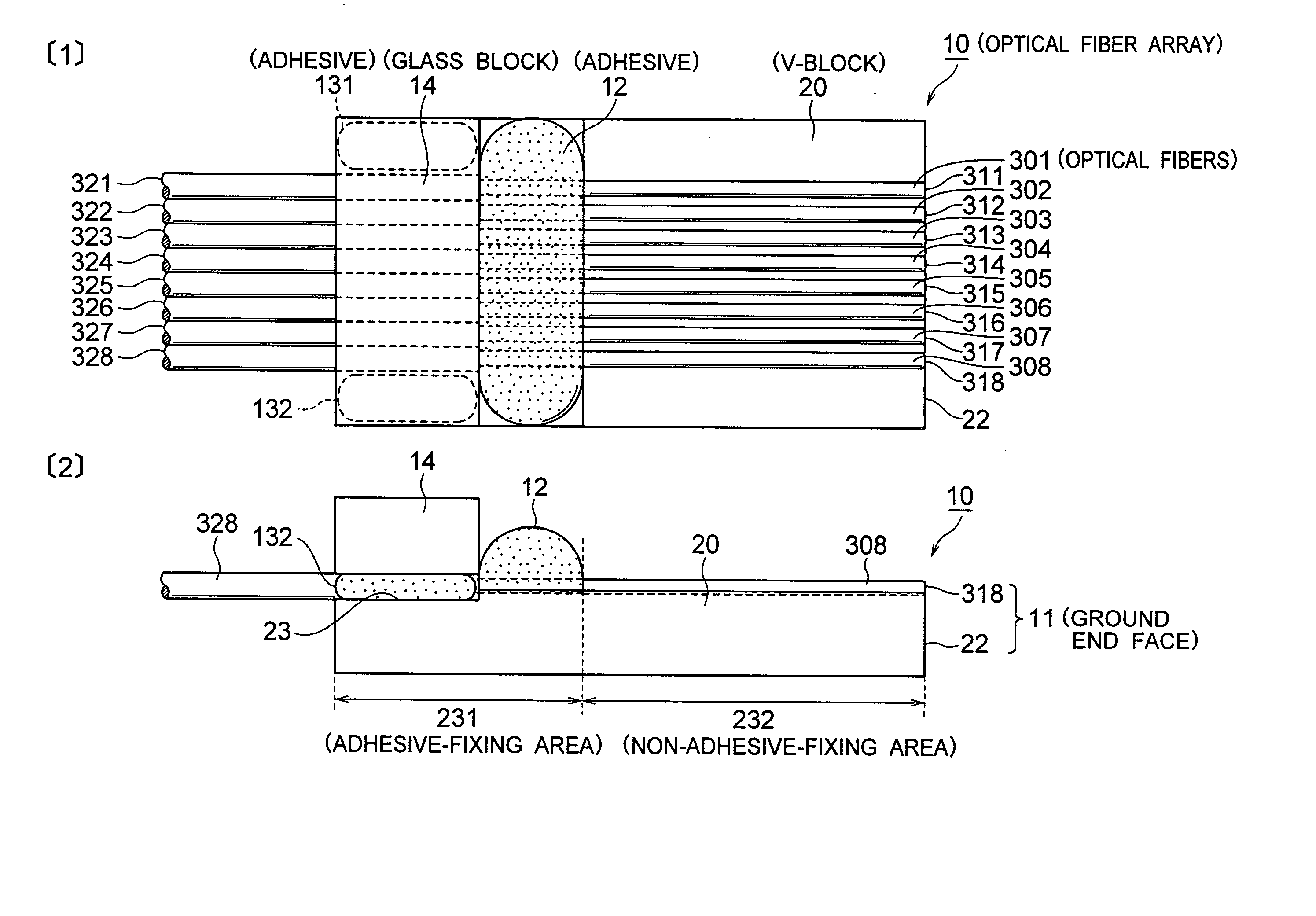
[0054] An optical fiber array 10 in this embodiment comprises a V-block 20 in which a plurality of V-grooves 211-218 are formed and optical fibers 301-308 that are fit individually into the V-grooves 211-218. The optical fibers 301-308 are fit in the V-grooves 211-218 with their end faces 311-318 flush approximately with an end face 22 of the V-block 20. The end face 22 of the V-block 20, including the end faces 311-318 of the optical fibers 301-308, is shaped according to the end face of an object to which the optical fibers 301-308 are to be connected. A ground end face 11, composed of the end faces 311-318 of the opt...

second embodiment

[0084]FIG. 14 is a diagram showing a front view of an optical waveguide module according to the present invention and its manufacturing method. The process proceeds in order of FIG. 14 [1] to FIG. 14 [3]. The following describes this embodiment with reference to those drawings. Note that the same reference numerals as those in FIG. 11 denote the same structural elements and their descriptions are omitted.

[0085] As shown in FIG. 14 [3], the configuration of an optical waveguide module 60 in this embodiment is similar to that of the optical waveguide module 40 in the first embodiment except that an abutment block 61 is added. This abutment block 61 is provided on the PLC substrate 50 and has an abutment face 62 that is flush with the end faces 531-538 of the optical waveguides 511-518. The abutment block 61, made of a glass substrate or a silicon substrate, is fixed on the PLC substrate 50 with an adhesive, for example, and the abutment face 62 is formed at the same time the slit 57 i...


PUM


Abstract

Optical fibers 301-308 are housed in V-grooves formed on a V-block 20 with end faces 311-318 flush with an end face 22 of the V-block 20. Therefore, when the optical fibers 301-308 are connected to optical waveguides, the V-block 20 suppresses the oscillation of the end faces 311-318 of the optical fibers 301-308. This structure increases the alignment precision and increases the intensity of the optical fibers 301-308.

Description

BACKGROUND OF THE INVENTION [0001] 1. Field of the Invention [0002] The present invention relates to an optical fiber component advantageously applicable to the passive alignment technology. [0003] 2. Description of the Related Art [0004] Recently, many optical components based on the PLC (Planar Lightwave Circuit) technology are widely used such as an AWG (Arrayed Waveguide Grating), a VOA (Variable Optical Attenuator), and an optical splitter. Those optical components, each with an interferometer or an optical branching unit within an optical circuit, can be combined to configure an optical filter or an optical attenuator. Thus, those optical components are important as key devices in an optical communication system. [0005] To connect a PLC-based optical component to an optical fiber, the optical fiber is usually connected directly to the optical component with an adhesive. An appropriate adhesive, if used for this connection structure, would ensure good characteristics of connect...

Claims


Application Information

Patent Timeline
Patent Type & Authority Applications(United States)
IPC IPC(8): G02B6/24G02B6/00G02B6/30G02B6/36
CPCG02B6/30G02B6/3692G02B6/3652G02B6/3636
Inventor WATANABE, SHINYA
Owner NEC CORP
Why Eureka
Try Eureka